
Devices for harvesting energy from electromagnetic radiation

a technology of electromagnetic radiation and energy harvesting device, which is applied in the direction of optical radiation measurement, light radiation electric generator, instruments, etc., can solve the problems of limited energy collection in low-light, limited photovoltaic cells, and limited photovoltaic cells

Active Publication Date: 2011-11-17
BATTELLE ENERGY ALLIANCE LLC
View PDF1 Cites 46 Cited by
  • Summary
  • Abstract
  • Description
  • Claims
  • Application Information

AI Technical Summary

Benefits of technology

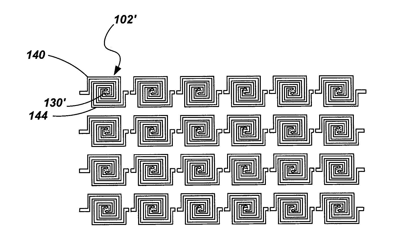
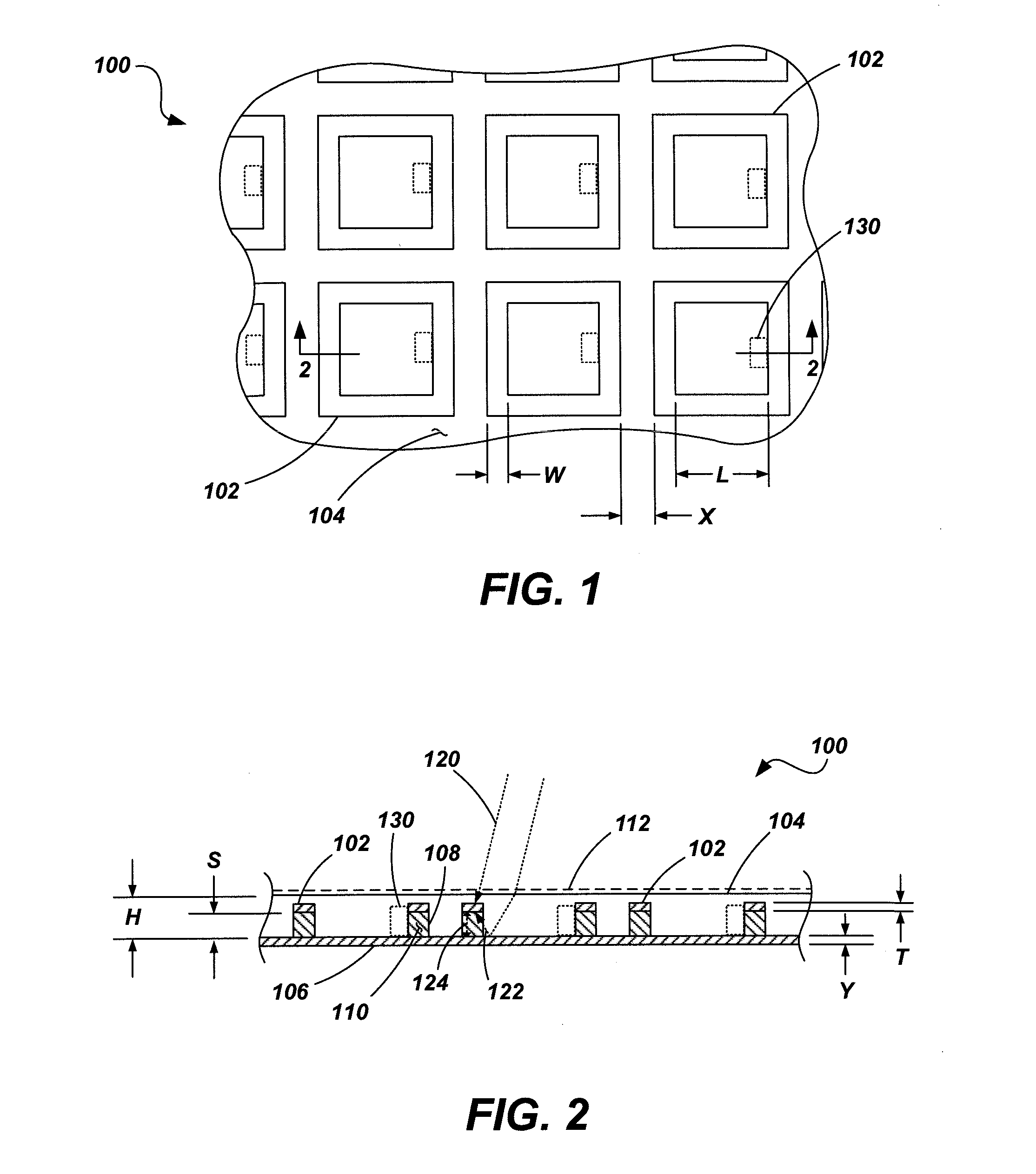
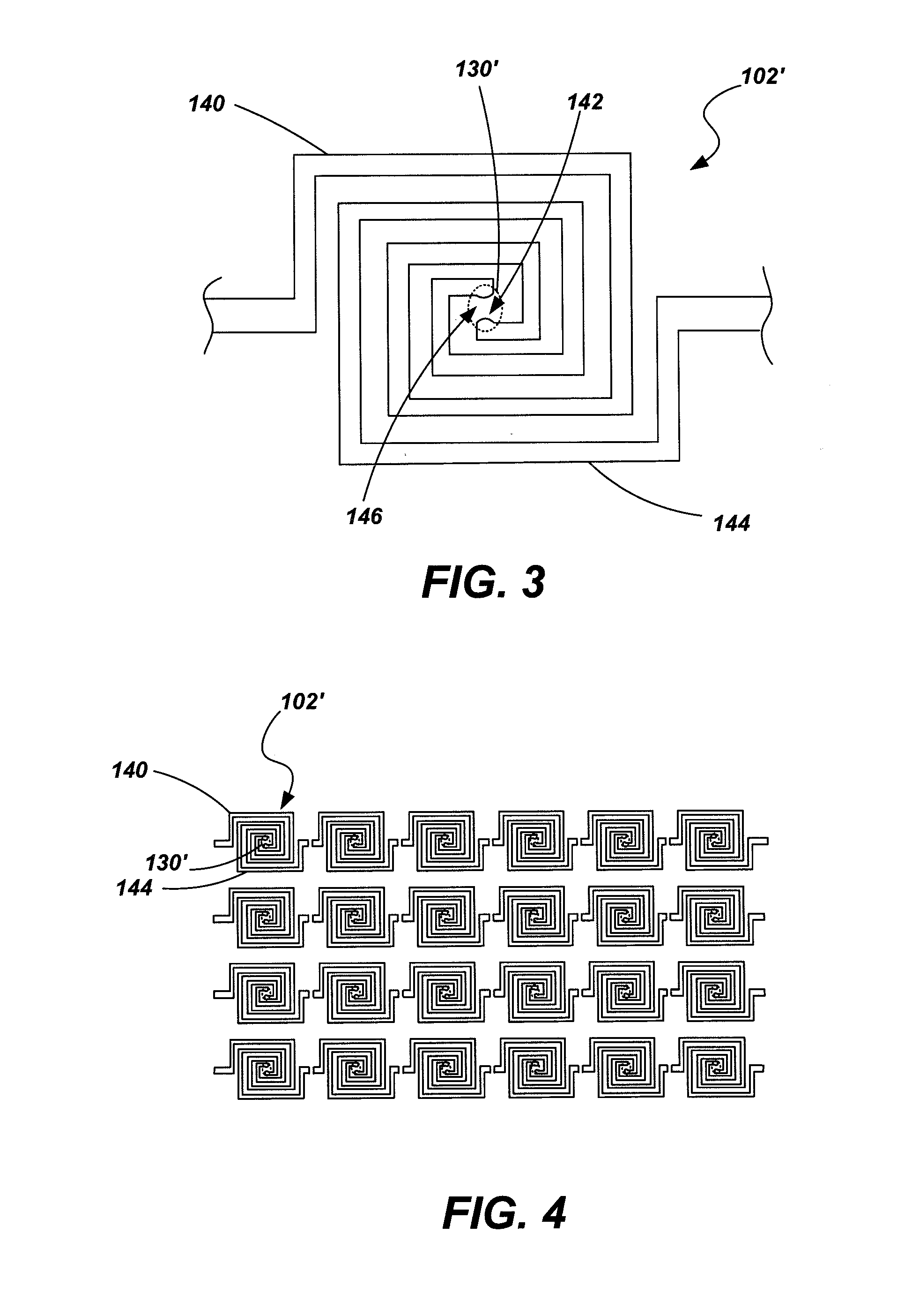
The present invention provides an energy harvesting device that can capture and convert electromagnetic radiation to AC energy. The device includes a resonance element made of conductive material with a resonant frequency between 20 THz and 1,000 THz. The device can be exposed to electromagnetic radiation and the resonance element absorbs a portion of the radiation while reflecting off of a surface. The induced AC energy is then transferred via an energy transfer element. The invention also provides a method of harvesting energy by exposing a resonance element to electromagnetic radiation from the earth. The technical effects of the invention include efficient energy conversion and a wide range of applications.

Problems solved by technology

Such energy collection is limited in low-light conditions such as at night or even during cloudy or overcast conditions.
Conventional solar technologies are also limited with respect to the locations and orientations of installment.
Additionally, current photovoltaic cells are relatively large and are limited in where they may be installed.
As such, while providing some utility in harvesting energy from the electromagnetic radiation provided by the sun, current solar technologies are not yet developed to take full advantage of the potential electromagnetic energy available.
Further, the apparatuses and systems used in capturing and converting solar energy are not particularly amenable to installation in numerous locations or situations.
Moreover, photovoltaic cells are conventionally limited to collection of energy in a very narrow band of light (e.g., approximately 0.8 micrometer to 0.9 micrometer (μm) wavelengths).
Current energy harvesting technologies fail to take advantage of such available energy.
As previously discussed, there is a large amount of renewable electromagnetic radiation available that has been largely untapped as an energy source using currently available techniques.
However, the scaling of existing FSSs or other similar structures for use in harvesting such potential energy sources comes at the cost of reduced gain for given frequencies.
Additionally, scaling FSSs or other transmitting or receptive structures for use with, for example, the IR or near-IR spectra presents numerous challenges due to the fact that materials do not behave in the same manner at the so-called “nano-scale” as they do at scales that enable such structures to operate in, for example, the radio frequency (RF) spectra.

Method used


Image

  • Devices for harvesting energy from electromagnetic radiation
  • Devices for harvesting energy from electromagnetic radiation
  • Devices for harvesting energy from electromagnetic radiation

Examples


Embodiment Construction

[0030]In the following detailed description, reference is made to the accompanying drawings which form a part hereof, and in which is shown by way of illustration specific embodiments in which the invention may be practiced. These embodiments are described in sufficient detail to enable those of ordinary skill in the art to practice the invention. It should be understood; however, that the detailed description and the specific examples, while indicating examples of embodiments of the invention, are given by way of illustration only and not by way of limitation. From this disclosure, various substitutions, modifications, additions, rearrangements, or combinations thereof within the scope of the present invention may be made and will become apparent to those skilled in the art.

[0031]Embodiments of the present invention provide methods, structures and systems for harvesting energy from electromagnetic radiation including, for example, harvesting energy from radiation in the infrared, n...


PUM


Abstract

Methods, devices and systems for harvesting energy from electromagnetic radiation are provided including harvesting energy from electromagnetic radiation. In one embodiment, a device includes a substrate and one or more resonance elements disposed in or on the substrate. The resonance elements are configured to have a resonant frequency, for example, in at least one of the infrared, near-infrared and visible light spectra. A layer of conductive material may be disposed over a portion of the substrate to form a ground plane. An optical resonance gap or stand-off layer may be formed between the resonance elements and the ground plane. The optical resonance gap extends a distance between the resonance elements and the layer of conductive material approximately one-quarter wavelength of a wavelength of the at least one resonance element's resonant frequency. At least one energy transfer element may be associated with the at least one resonance element.

Description

CROSS-REFERENCE TO RELATED APPLICATIONS[0001]This application is a divisional of U.S. patent application Ser. No. 11 / 939,342, filed Nov. 13, 2007, pending, which application is related to U.S. patent application Ser. No. 11 / 939,358 filed Nov. 13, 2007, now U.S. Pat. No. 7,792,644, issued Sep. 7, 2010, entitled METHODS, COMPUTER READABLE MEDIA, AND GRAPHICAL USER INTERFACES FOR ANALYSIS OF FREQUENCY SELECTIVE SURFACES, and U.S. Provisional Patent Application Ser. No. 60 / 987,630 filed Nov. 13, 2007, entitled ANTENNA DEVICES COMPRISING FLEXIBLE SUBSTRATES, RELATED STRUCTURES, AND METHOD OF MAKING AND USING THE SAME, the entire disclosure of each of which is hereby incorporated herein by this reference.GOVERNMENT RIGHTS[0002]This invention was made with government support under Contract No. DE-AC07-05-ID14517 awarded by the United States Department of Energy. The government has certain rights in the invention.TECHNICAL FIELD[0003]Embodiments of the present invention relate generally to ...

Claims


Application Information

Patent Timeline
Patent Type & Authority Applications(United States)
IPC IPC(8): H02N6/00
CPCH01Q1/248H02S99/00H01Q21/061Y02E10/50
Inventor NOVACK, STEVEN D.KOTTER, DALE K.PINHERO, PATRICK J.
Owner BATTELLE ENERGY ALLIANCE LLC
Learn More