
Medical Device for Anchoring a Guidewire During a Percutaneous Coronary Intervention

a technology of guidewires and medical devices, which is applied in the direction of guide wires, catheters, etc., can solve the problems of not providing any support for advancing devices over portentous, affecting the safety of patients,

Inactive Publication Date: 2011-11-10
AL RASHDAN IBRAHIM R
View PDF3 Cites 3 Cited by
  • Summary
  • Abstract
  • Description
  • Claims
  • Application Information

AI Technical Summary

Benefits of technology

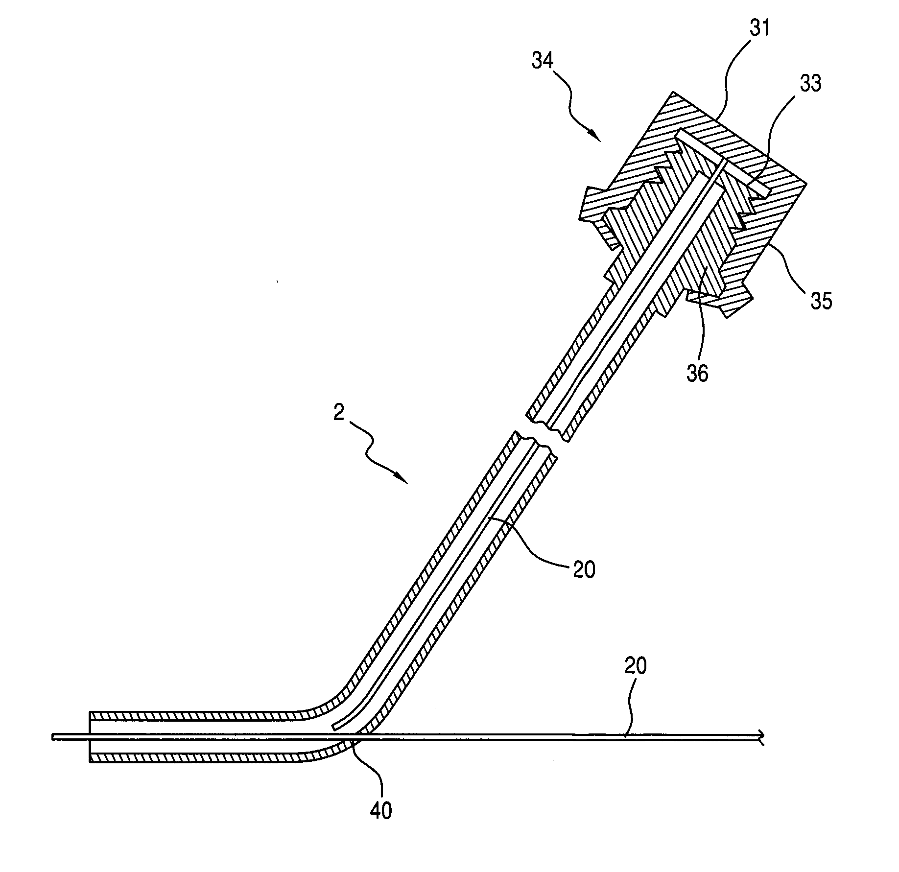
[0023]FIG. 1 is a schematic illustration of a conventional anchor on a proximal end of a medical device that includes a cathet

Problems solved by technology

During Percutaneous Coronary Intervention (PCI) an interventional cardiologist introduces a guidewire into the coronary artery, passed the diseased segment and subsequently advances interventional devices such as a dilation balloon and / or stent to a target over the wire as the guide wire is free floating in the distal vessel, it does not provide any support for advancing devices over a portentous path in route to the target location.
If the angle of the bend has to be adjusted the guidewire must be removed, re-bent and reinserted sometimes several times. Particular difficulty is encountered pre-bending where an artery branches at one angle and then sub-branches at a different angle.
This procedure is attended by the risk of significant trauma to the arterial lining and in many cases the obstruction can not be reached at all with a guidewire and catheter.
Consequently the cardiologist often finds it very difficult to maneuver the guidewire or catheter which is typically several feet long from the proximal end.
Steering the pre-bent guidewire is further complicated by the fact that branches project at all different radial angles, thus necessitating rotation of the guidewire to the appropriate degree to enter the desired arterial branch.
However, rotation of the distal end of the wire typically lags behind rotation of the proximal control end so that precise rotational control is not possible.
Also, friction in the arteries can cause the distal end to rotate in a jerky fashion which can traumatize the vascular intima.

Method used


Image

  • Medical Device for Anchoring a Guidewire During a Percutaneous Coronary Intervention
  • Medical Device for Anchoring a Guidewire During a Percutaneous Coronary Intervention
  • Medical Device for Anchoring a Guidewire During a Percutaneous Coronary Intervention

Examples


Embodiment Construction

[0026]During percutaneous coronary interventions, the interventional cardiologist introduces a guide wire into the coronary artery past the diseased segment, and subsequently interventional devices such as dilation balloon and stents are advanced to the target location for therapy over the wire as a monorail system.

[0027]As the guide wire is floating free in the distal vessel it does not provide any support for advancing devices over a tortuous or angulated path in route to the target location. Few interventional techniques are used to facilitate device passage over resistant areas and no device is available to Applicant's knowledge to address this demanding challenge.

[0028]During percutaneous coronary interventions, as the proximal part of the guide wire is secured outside of the body, anchoring the guide wire in the distal vessel past the target location will add support for device delivery akin to a tight wire with both of its ends secure. However, in the present case the wire an...


PUM


Abstract

A medical device for anchoring a distal end of a guidewire in a catheter within a coronary artery during a Percutaneous Coronary Intervention including a catheter for being introduced into a coronary artery and a guidewire extending through the catheter. A first anchor device is provided at the proximal end of the guidewire outside of a patient's body and a second anchor is provided at the distal end of the guidewire and catheter to facilitate the movement of interventional devices in the body.

Description

FIELD OF THE INVENTION[0001]This invention relates to a medical device and / or method for anchoring a guidewire during a Percutaneous Coronary Intervention and more particularly to a device for holding the wire in a distal vessel without using the vessel as a ground for support and therefore avoiding vessel injuries.BACKGROUND FOR THE INVENTION[0002]Percutaneous Coronary Interventions (PCI) are a well known medical procedure and have been in use since as early as 1977. The procedure is commonly used to reduce or eliminate the symptoms of coronary artery disease including angina (chest pain), dyspnea (shortness of breath) on exertion, and congestive heart failure. PCI is also used to abort an acute myocardial infraction and in some specific cases it may reduce mortality.[0003]Percutaneous Coronary Interventions are also referred to as balloon angioplasty and are commonly used for the inflation of a balloon within a coronary artery to crush the plaque into the walls of an artery. While...

Claims


Application Information

Patent Timeline
IPC IPC(8): A61M25/09
CPCA61M25/09
Inventor AL-RASHDAN, IBRAHIM R.
Owner AL RASHDAN IBRAHIM R
Learn More