System and Method to Collect Status Information From Light Based Indicator Systems Such as Stack Lights, Status Lights, Traffic Lights, Safety Lights

Inactive Publication Date: 2011-11-10
ILS TECH INC
View PDF7 Cites 7 Cited by
  • Summary
  • Abstract
  • Description
  • Claims
  • Application Information

AI Technical Summary

Benefits of technology

[0015]While light sensing systems are common, they are typically designed where the light sensing is built into a product as part of its function. In the disclosed system and method, the light sensing is added to existing equipment after production or installation to provide a secondary function. The disclosed system and method also allows for tuning the sensitivity of the system to accommodate various situations such as, for example, low light factories or bright light traffic intersections.
[0017]Rather than relying on a production supervisor or other personnel to physically walk the production floor and monitor the actual tools by viewing the stack lights, through use of the disclosed system and method, the stack light status can be automatically read and the data sent to a central location for monitoring. This is particularly advantageous in the case of harsh or dangerous production environments, where it is desirable to minimize the number of people in the environment. Centralizing the tool data also has the advantage of being able to develop standard responses to production problems. Further still, centralization is also useful when the equipment manufacturer wants to know a summary of tool reported behavior over time, as the monitored data can be saved and a trend of the status can be created and analyzed.
[0033]In one form, the plurality of light sensors are movably attached to a base member mountable adjacent to the existing light based indicator system. In this manner, the plurality of light sensors may be positioned to accurately sense the status of an associated indicator light. The plurality of light sensors may be provided in a one-to-one relationship with the plurality of indicator lights, such that one light sensor monitors the status of one indicator light.
[0042]It is still a further object of the disclosed system and method to provide monitoring of an external light based indicator system allowing for adjustment of the position of the light indictor sensors.

Problems solved by technology

While there are light sensors available in the industry, they are generally used to detect a unit of work being present at a workstation or simply count items passing by them; they are neither used nor designed for the detection of status conditions of existing status indicator lights.

Method used


Image

  • System and Method to Collect Status Information From Light Based Indicator Systems Such as Stack Lights, Status Lights, Traffic Lights, Safety Lights
  • System and Method to Collect Status Information From Light Based Indicator Systems Such as Stack Lights, Status Lights, Traffic Lights, Safety Lights
  • System and Method to Collect Status Information From Light Based Indicator Systems Such as Stack Lights, Status Lights, Traffic Lights, Safety Lights

Examples


Embodiment Construction

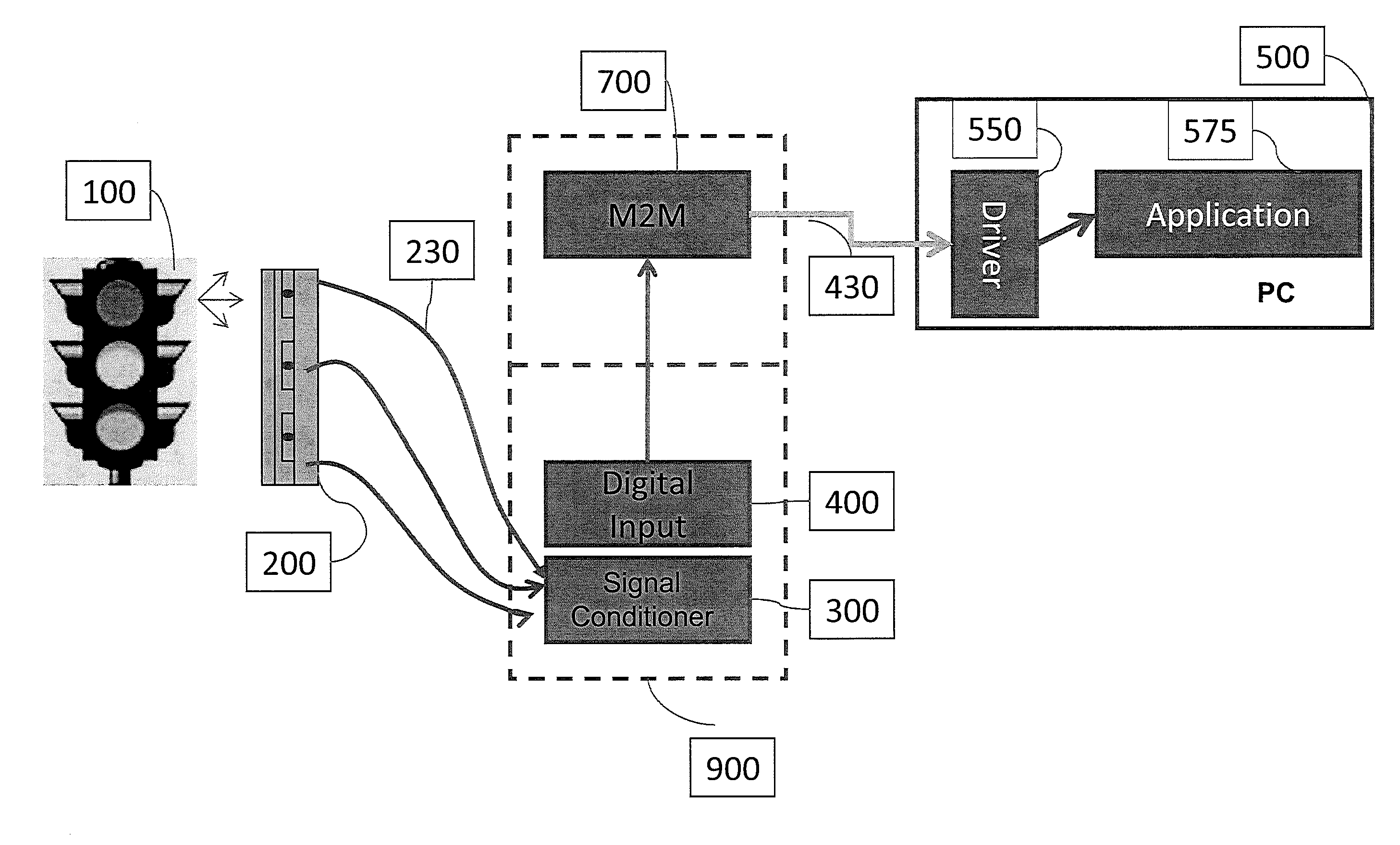
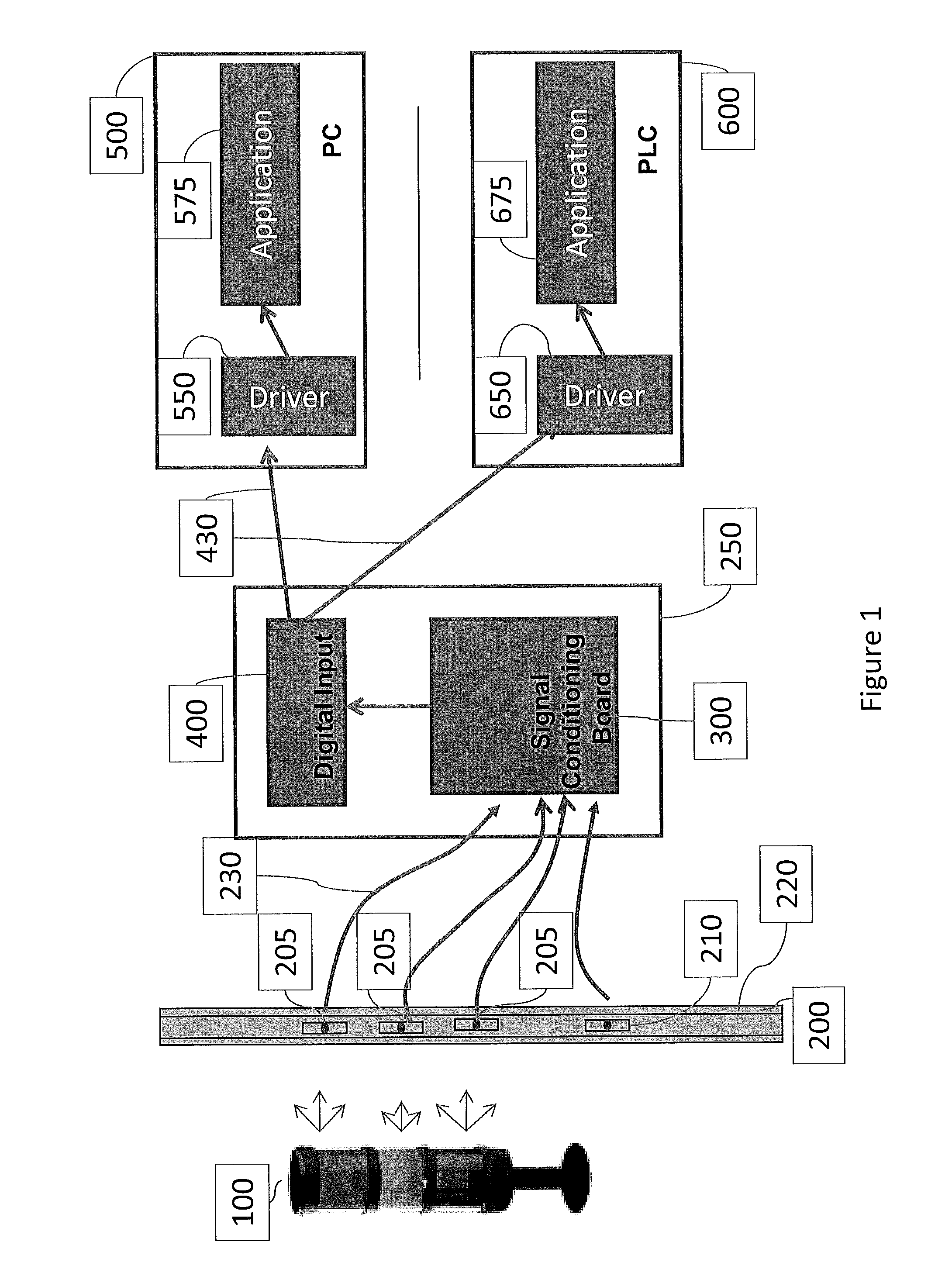
[0052]The basic components of the inventive system are shown in FIG. 1, which includes a stack light, or other light based indicator system, 100, a light sensor assembly 200, signal conditioner 250 which includes signal compensation circuitry 300 and a digital input 400, and a monitoring device in the form of a personal computer (“PC”) 500 having a software driver 550 and an application 575, and / or an alternate hardware platform such as a programmable logic controller (“PLC”) 600 having an onboard driver 650 and an application 675. The connection wiring 230 from the light sensor 200 to the signal compensation circuitry 300 and the wiring 430 from the digital input 400 to the PC 500 and / or PLC 600 is also shown in FIG. 1.

[0053]The stack lights or light indicators 100 are standard additions to factory equipment to quickly let the operators know how the machinery is operating based on a visual indication of the lights. For example, green typically indicates proper operation, red typica...


PUM


Abstract

A system and method for monitoring status information from a light based indicator system (e.g., stack lights, status lights, traffic lights or safety lights, etc.). At least one light sensor is positioned adjacent to an existing light indicator system, the existing light based indicator system having at least one indicator light to be monitored. A monitoring device at a location remote from the existing light based indicator system receives signals from the at least one light sensor indicative of a status of the at least one indicator light.

Description

CROSS-REFERENCE TO RELATED APPLICATIONS[0001]This application claims the benefit of co-pending Provisional Patent Application Ser. No. 61 / 331,450 entitled “System and Method to Collect Statue Information from Light Based Indicator Systems Such as Stack Lights and Status Lights”, filed on May 5, 2010, the entire disclosure of which is incorporated by reference herein.FIELD OF THE INVENTION[0002]The present invention is directed generally toward the monitoring of light indicator systems and, more particularly, toward the automatic monitoring of light indicator systems indicative of various conditions.BACKGROUND OF THE INVENTION[0003]In many industries, equipment is initially installed and control and monitoring systems are integrated to this equipment and a production line is brought up. An example of a type of monitoring equipment is a stack light, which is generally used to indicate the operational status of a machine. The stack light could have one light to indicate the operational...

Claims


Application Information

Patent Timeline
Patent Type & Authority Applications(United States)
IPC IPC(8): G08B21/00G01J1/44
CPCG01J1/4204G01J1/32
Inventor KEEVER, JOHNLUNDE, DENNIS
Owner ILS TECH INC
Why Eureka
Try Eureka