
Device and method for storing heat

a technology for storing devices and heat storage mediums, applied in indirect heat exchangers, lighting and heating apparatuses, transportation and packaging, etc., can solve the problems of large outlay, undesired deposits, and high pressure owing to the design of containers, and achieve the effect of reliably operating

Inactive Publication Date: 2011-11-10
BASF AG
View PDF27 Cites 39 Cited by
  • Summary
  • Abstract
  • Description
  • Claims
  • Application Information

AI Technical Summary

Benefits of technology

[0010]It is an object of the present invention to provide a device for storing heat, which does not have the disadvantages known from the prior art and can be operated reliably even at high temperatures.

Problems solved by technology

The prevalence of high pressures owing to the design of the container necessitates great outlay.
Even in small concentrations, oxygen can lead to oxidation processes of the heat storage medium, in which case detrimental, for example insoluble products may be formed.
Undesired deposits can occur as a result of this.
The storage capacity of the heat storage medium is furthermore affected by the formation of insoluble products.
In the case of a combustible heat storage medium, a sufficiently large concentration of oxygen together with a significant vapor pressure can also lead to an explosion risk.
In particular when a gas overhead with an inert gas is necessary, high operating costs are involved.
The use of such gasometers, however, is problematic when using heat storage mediums having a significant vapor pressure, since the heat storage medium condenses into the gasometer.
These devices, however, are very elaborate to construct and operate.
Floating lids, however, generally are not made fully gastight and, for example, have wall seals with the container wall.
For use with the high temperatures of a heat storage tank, however, this solution is not sufficient.
When using heat storage mediums containing sulfur, sulfur dioxide and sulfur trioxide can be formed, which can damage the container walls by corrosion.

Method used


Image

  • Device and method for storing heat
  • Device and method for storing heat
  • Device and method for storing heat

Examples


first embodiment

[0026]In a first embodiment, the volume compensation means comprise a flexible cover of the container. The flexible cover of the container may, for example, be produced by a suitable container lid which is raised when there is a volume expansion of the heat storage medium and is lowered again when there is a volume decrease of the heat storage medium, without the seal on the edge of the cover being broken. In particular, it is possible for the flexible cover to comprise flexible regions, which expand when there is a volume increase of the heat storage medium and which contract when there is a volume decrease of the heat storage medium. The flexible regions of the lid may extend over the entire cover or alternatively only occupy parts of the cover. If the flexible regions only comprise parts of the cover, then it is possible for example for parts of the cover to be configured in the form of a compensator which can expand when there is a volume increase. Such a compensator has, for ex...

second embodiment

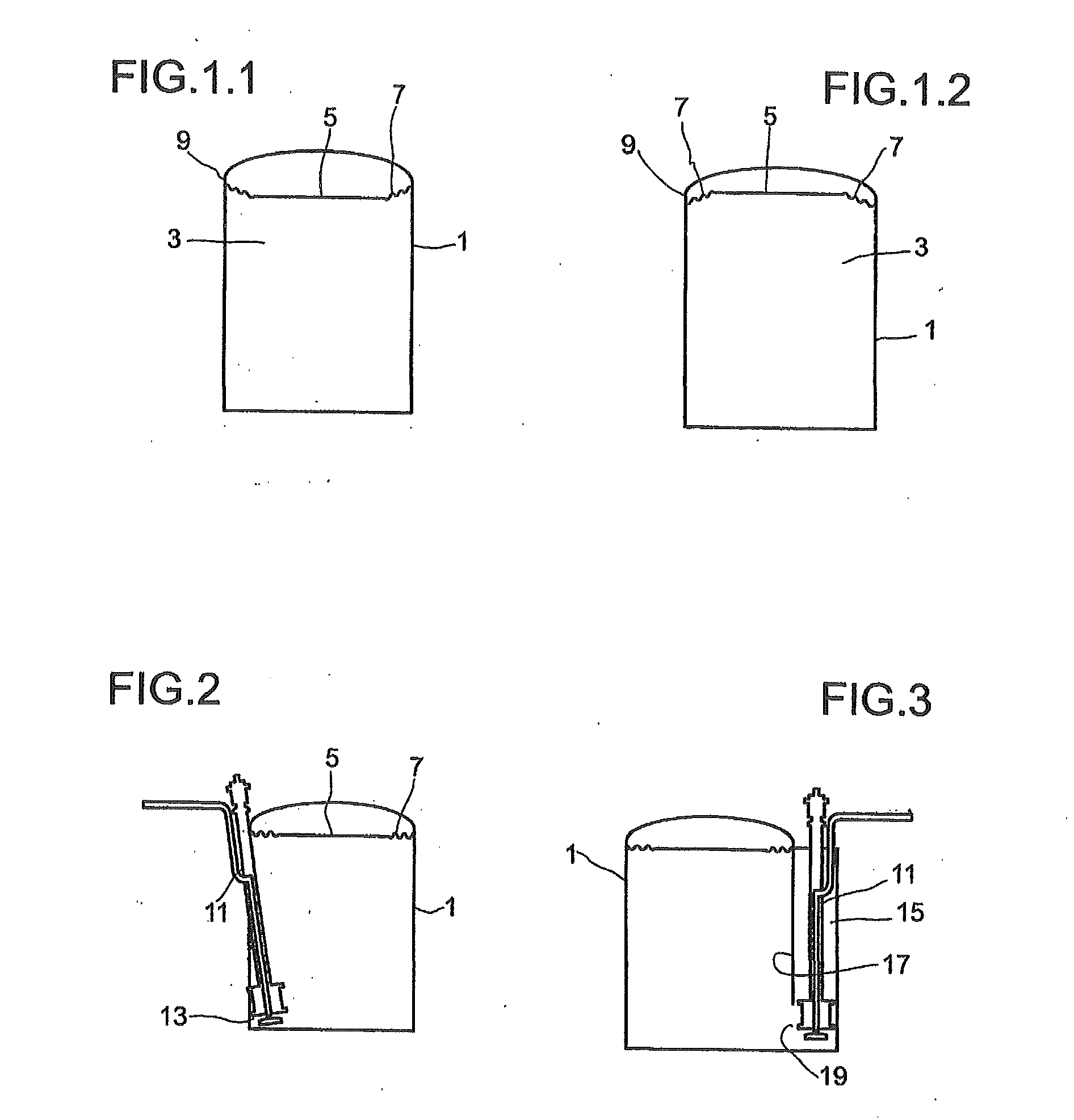
[0080]FIG. 3 shows a container for holding a heat storage medium, having a flexible cover and an immersion pump in a second embodiment,

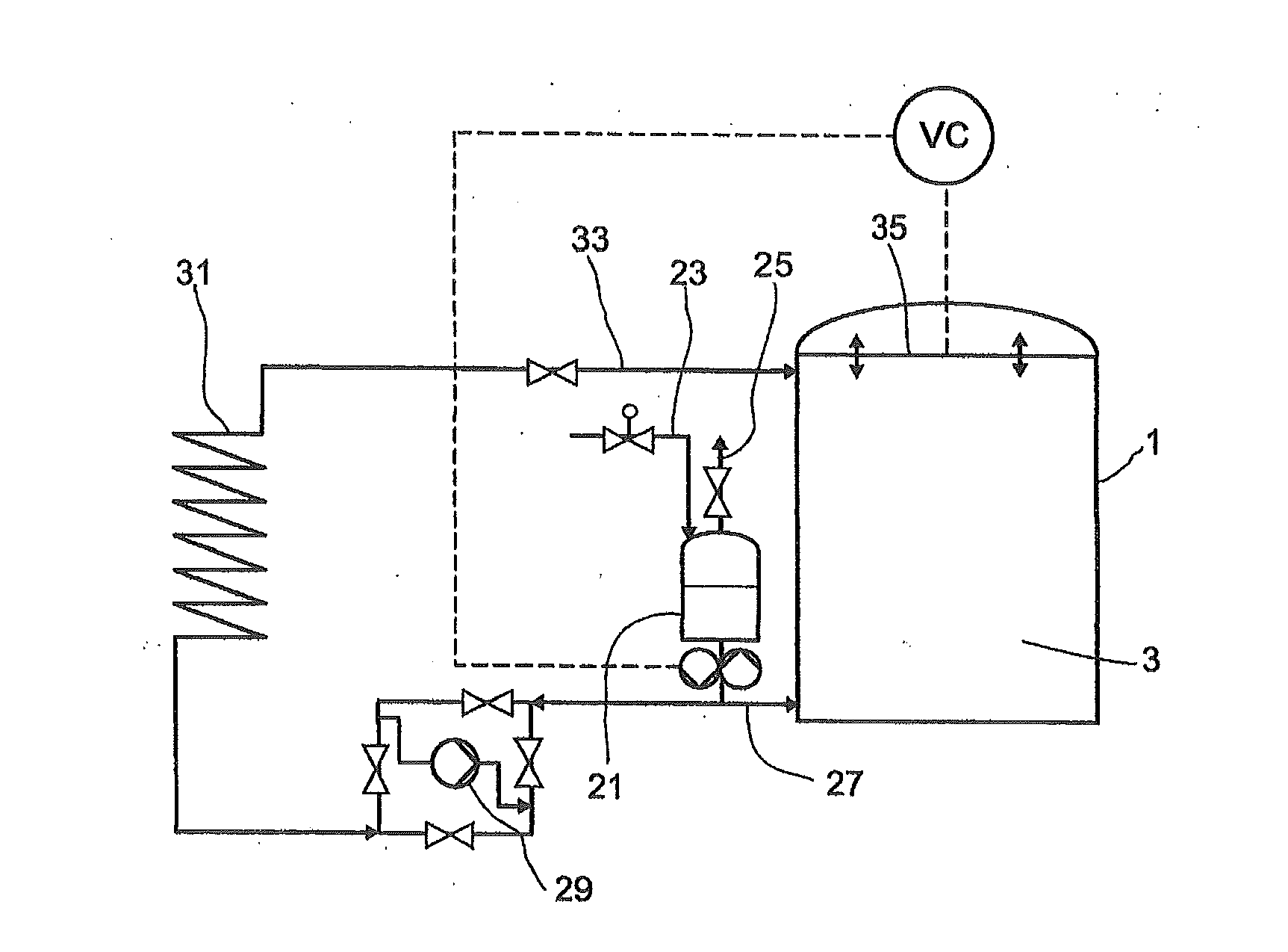
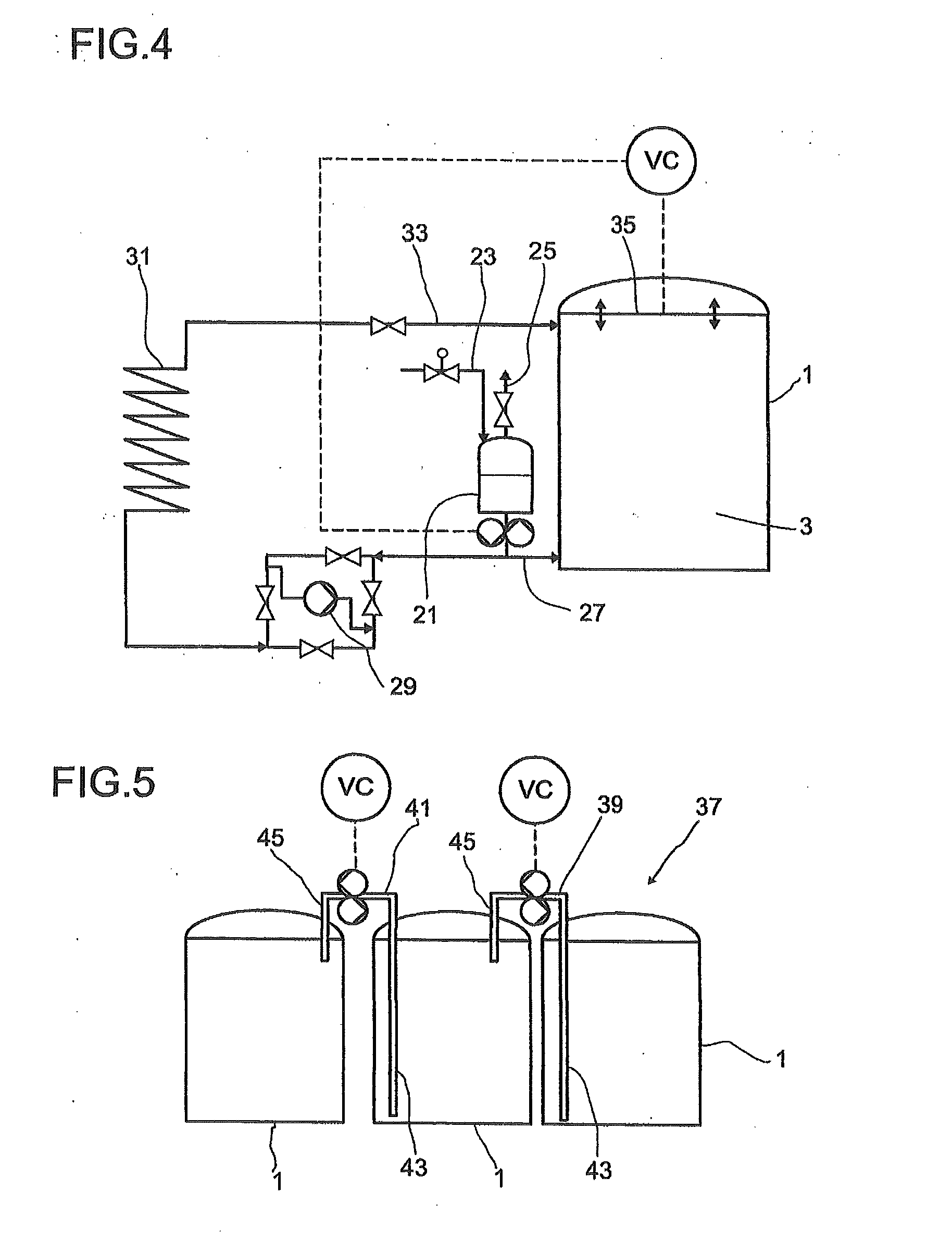
[0081]FIG. 4 shows a device for storing heat, having a buffer container,

[0082]FIG. 5 shows containers for holding a heat storage medium, as serial stratified storage tanks,

[0083]FIG. 6 shows a container for holding a heat storage medium, which is configured as a stratified storage tank,

[0084]FIG. 7 shows a manifold, as is used in a stratified storage tank according to FIG. 6, in plan view,

[0085]FIG. 8 shows two buffer containers connected in series,

[0086]FIG. 9 shows a container for holding a heat storage medium, which is combined integrally with a buffer container,

[0087]FIG. 10 shows a container for holding a heat storage medium, having buffer containers in another embodiment.

[0088]FIG. 1.1 shows a container for holding a heat storage medium, having a flexible cover and containing a cold heat storage medium. A container 1 is filled with a heat stora...


PUM


Abstract

The invention relates to a device for storing heat, comprising a heat storage medium which absorbs heat in order to store heat and releases heat in order to use the stored heat, and a container for holding the heat storage medium, the container being closed by a gastight cover, and the device comprising volume compensation means in order to compensate for a volume increase of the heat storage medium (3) due to a temperature rise and a volume decrease due to a temperature reduction. The invention furthermore relates to a method for storing heat, in which heat is transferred to a heat storage medium in order to store heat or heat is discharged from the heat storage medium to the heat carrier in order to use the heat, the heat storage medium being held in a container which is closed by a gastight cover, wherein a volume expansion of the heat storage medium (3) is compensated for by a volume increase of the container (1) or by heat storage medium (3) flowing out of the container (1) into a buffer container (21; 63, 65), and a volume decrease of the heat storage medium (3) is compensated for by a volume decrease of the container (1) or by heat storage medium (3) flowing out of the buffer container (21; 63, 65) into the container (1).

Description

CROSS-REFERENCE TO RELATED APPLICATIONS[0001]This application claims benefit (under 35 USC 119(e)) of U.S. Provisional application 61 / 330,953, filed May 4, 2010 which is incorporated by reference.BACKGROUND OF THE INVENTION[0002]The invention is based on a device for storing heat, comprising a heat storage medium which absorbs heat in order to store heat and releases heat in order to use the stored heat, and a container for holding the heat storage medium, the container being closed by a gastight cover. The invention is furthermore based on a method for storing heat, in which, in a heat exchanger, heat is transferred from a heat carrier to a heat storage medium or, in the heat exchanger, heat is discharged from the heat storage medium to the heat carrier, the heat storage medium being held in a container which is closed by a gastight cover.[0003]Devices and methods for storing heat are used, for example, in solar power stations. By using the device or method for storing heat, solar ...

Claims


Application Information

Patent Timeline
IPC IPC(8): F24J2/34B65D6/12F24J2/30F28D17/00F24S10/30
CPCF28D20/0034F28D20/0039Y02E60/142F28D2020/0069F28D2020/0091F28D2020/0047Y02E60/14
Inventor WORTMANN, JURGENSCHAFER, CLAUSLUTZ, MICHAELSEELER, FABIANGARTNER, MARTINMAJOR, FELIXSCHIERLE-ARNDT, KERSTINMACHHAMMER, OTTOHUBER, GUNTHERMAURER, STEPHAN
Owner BASF AG
Learn More