
Apparatus for bone fixation

a bone fixation and applicator technology, applied in the field of applicators for bone fixation, can solve the problems of screw loosening out of bone and plate, stress concentrated around screws,

Inactive Publication Date: 2011-11-03
SOLCO BIOMEDICAL +1
View PDF1 Cites 7 Cited by
  • Summary
  • Abstract
  • Description
  • Claims
  • Application Information

AI Technical Summary

Benefits of technology

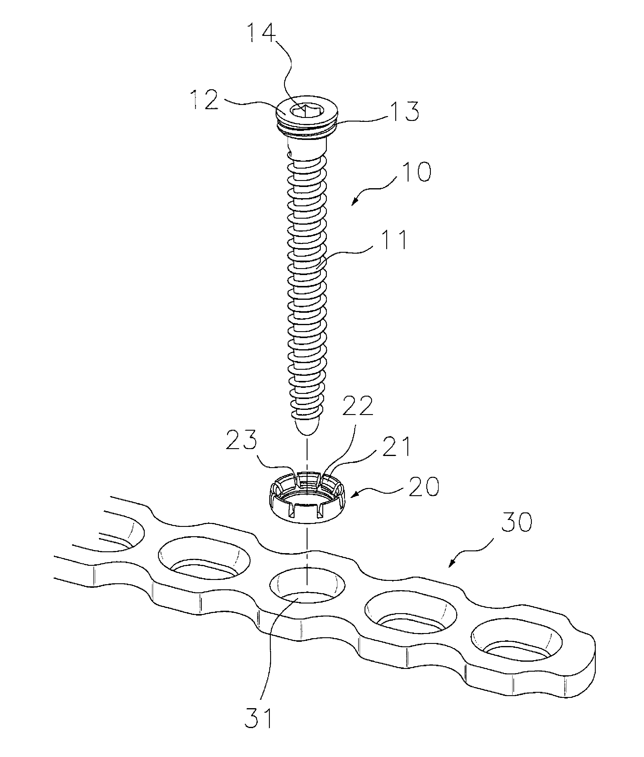
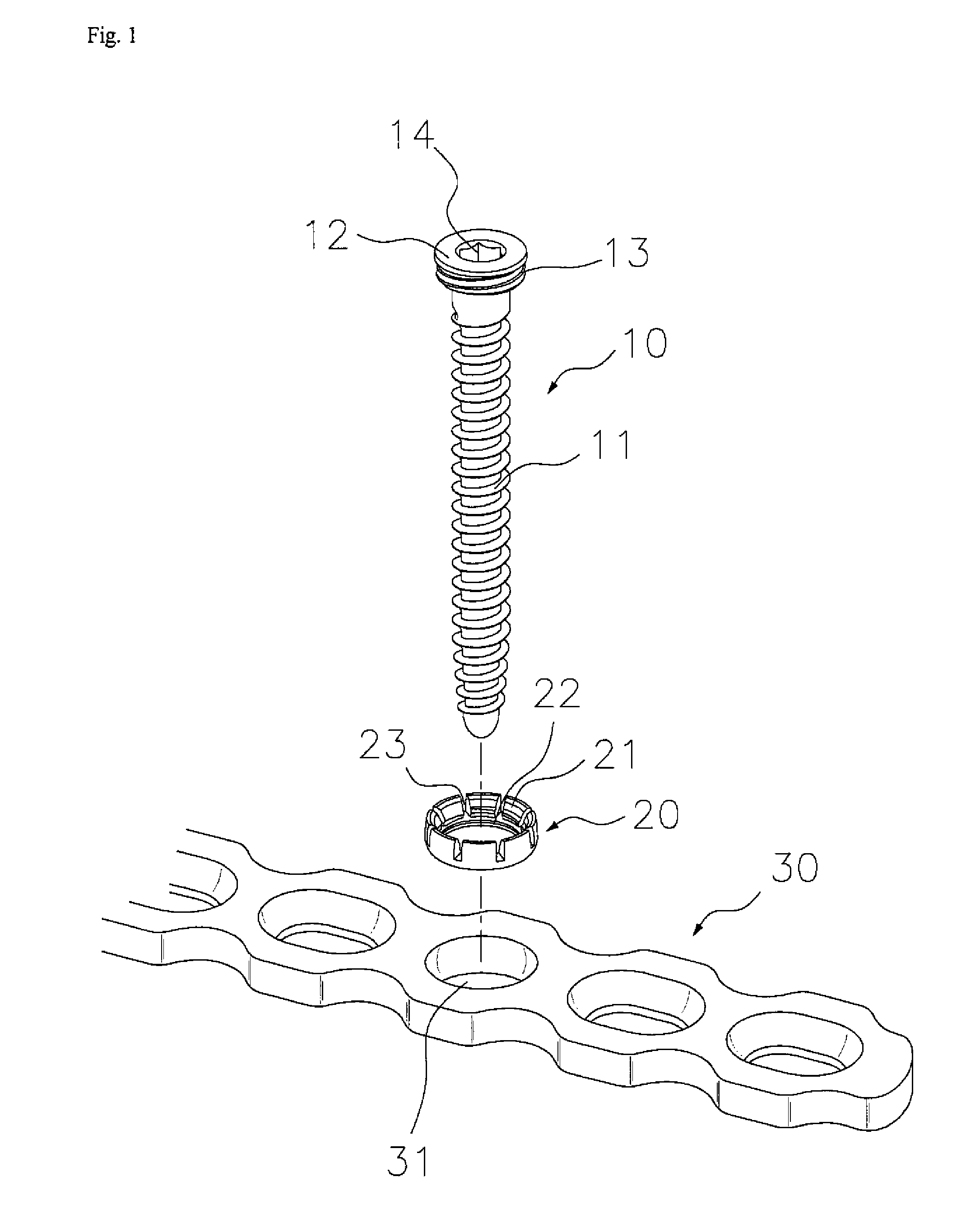
The apparatus for bone fixation according to the present invention has the effect of inserting and fixing the screw perpendicular to the plate because the washer and screw are combined in advance and then fixed to the plate, and allowing an operator to more freely perform an operation because the operator can insert and fix the screw at a desired angle.
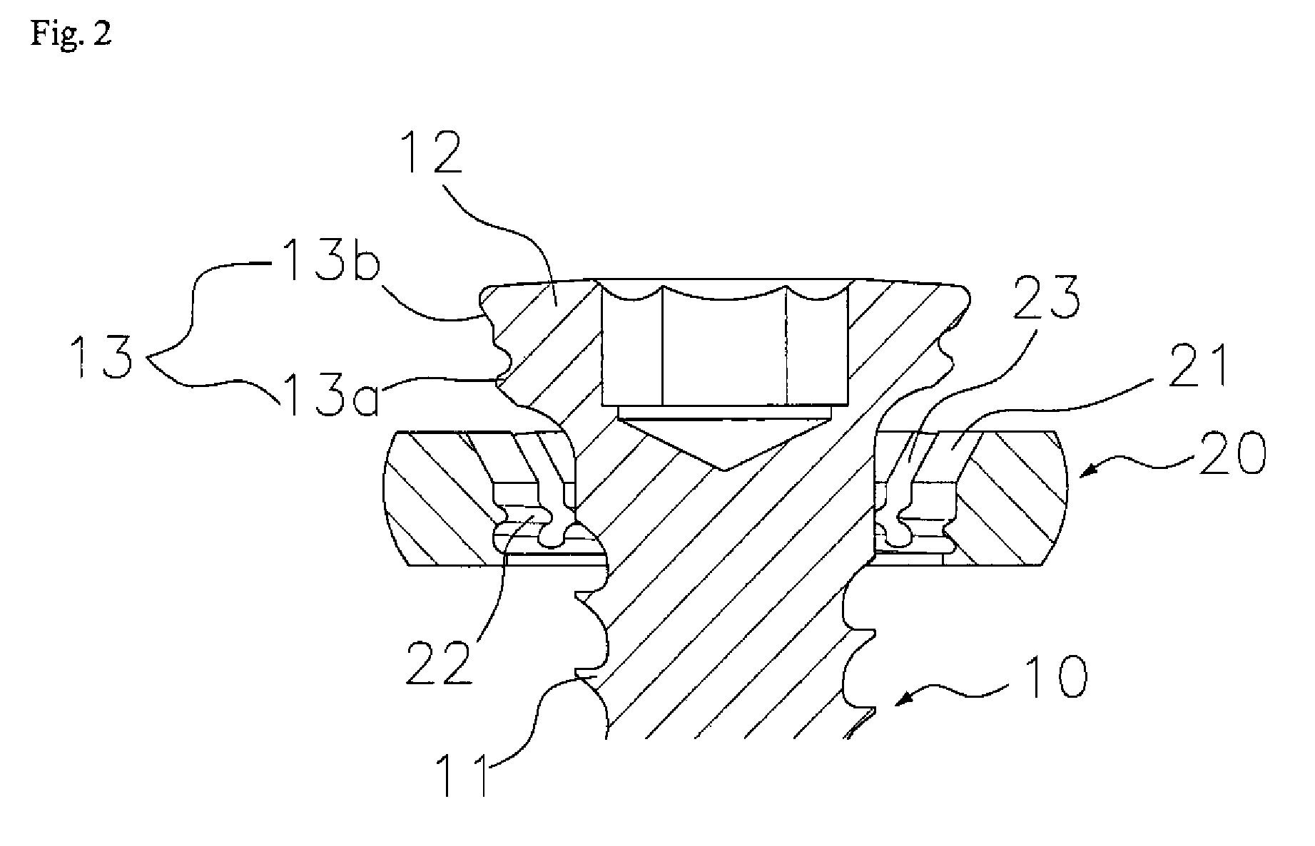
Since the washer of the present invention has the gaps, it can easily increase in diameter. A plurality of the gaps is formed at regular intervals and the upper end of the washer radially expands, such that it is stably fixed in the locking hole while preventing biasing to a side.
Further, the locking hole has a circular shape or a shape of which both sides are semicircular shapes facing each other at a predetermined distance, which allows an operator to be able to adjust the position and insertion angle of the screw in more detail, if necessary.

Problems solved by technology

However, there was a problem in that when the apparatuses for bone fixation in the related art are used over a long period of time after being transplanted into the patient's body, stress is concentrated around the screws due to external load, such that the screws loosen out of the bone and the plate.

Method used


Image

  • Apparatus for bone fixation
  • Apparatus for bone fixation
  • Apparatus for bone fixation

Examples


Embodiment Construction

However, according to the locking system in the related art, it is impossible to adjust the insertion angle of the screw because the shape and insertion direction of the thread formed in the hole of the plate are fixed. Further, a drill guide that is threaded is connected to the inlet of the hole of the plate to insert the screw while maintaining a predetermined angle and the screw has to penetrate the bone, which needs to be transplanted, such that the work is complicated and time is unnecessarily wasted.

Further, after the bone fracture is repaired, the thread of the head portion of the screw sticks to the thread of the plate hole, such that it may be impossible to remove the screw. In this case, since it is required to cut the plate itself to be removed, several problems are generated, such as the cut area of the soft tissue increases, the operation time becomes long, and equipment for cutting the plate is needed. Furthermore, there is a risk in causing additional bone fractures w...


PUM


Abstract

The present invention is characterized in that an apparatus for bone fixation that is composed of a plate and screws fixing the plate to a bone, includes: screws that has a head portion having a male thread on the outer circumference while increasing in diameter toward the upper portion in a tapered shape; washers of which the outer circumference is formed convex, and which has, on the inner circumference, a slope that contact with the head portion such that the head portion of the screw is placed and a female thread that is engaged with the male thread of the head portion; and a plate that has locking holes which are bored concave in the up-down direction and have a holding step, where the washer is placed, on the inner circumference, in which when the washer and the head of which the female thread and the male thread are partially engaged are inserted from above the locking hole and placed on the holding step, as the head portion is moved down by thread-fastening, the washer is in close contact and fixed in the locking hole while the diameter of the upper end increases, and the apparatus for bone fixation according to the present invention has the effect of inserting and fixing the screw perpendicular to the plate because the washer and screw are combined in advance and then fixed to the plate, and allowing an operator to more freely perform an operation because the operator can insert and fix the screw at a desired angle.

Description

BACKGROUND OF THE INVENTIONThe present invention relates to an apparatus for bone fixation that joins broken bones, more particularly an apparatus for bone fixation designed to allow an operator to more freely perform an operation.In general, for treating a bone fracture, apparatuses for bone fixation, which disposes and fix a plate to the surface of a broken bone with screws, for treatment, after the soft tissue of a bone fracture patient is cut, is used.These apparatuses for bone fixation generally have structures in which holes are formed through a plate and screws are inserted in the holes.However, there was a problem in that when the apparatuses for bone fixation in the related art are used over a long period of time after being transplanted into the patient's body, stress is concentrated around the screws due to external load, such that the screws loosen out of the bone and the plate. Reoperation was required, particularly for patients with osteoporosis.SUMMARY OF THE INVENTIO...

Claims


Application Information

Patent Timeline
IPC IPC(8): A61B17/80
CPCA61B17/8047
Inventor OH, JONG-KEONKIM, SEO-KONKIM, IL
Owner SOLCO BIOMEDICAL
Learn More