
Lighting device

Inactive Publication Date: 2011-11-03
BLV LICHT UND VAKUUMTECHNIK GMBH
View PDF6 Cites 2 Cited by
  • Summary
  • Abstract
  • Description
  • Claims
  • Application Information

AI Technical Summary

Benefits of technology

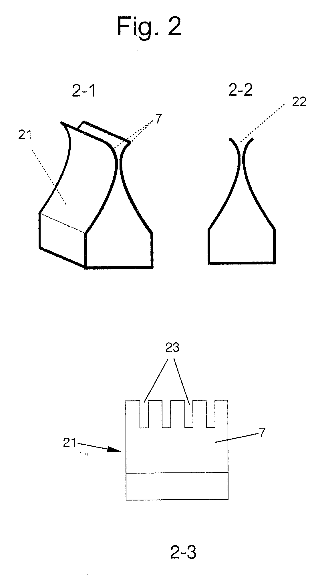
[0008]The advantages achieved by the invention are, in particular, that due to the special implementation of lamp sockets and terminal receptacles, and particularly, the elements which produce the electrical contact between the two, the susceptibility to corrosion is significantly reduced and a permanent electrical contact is ensured. This significantly lengthens the lifetime of the lighting device.
[0017]Another aspect of the invention provides a measure to further reduce the temperature and thus increase the lifetime.

Problems solved by technology

This significantly lengthens the lifetime of the lighting device.

Method used


Image

  • Lighting device
  • Lighting device
  • Lighting device

Examples


Embodiment Construction

[0024]The invention is explained hereafter on the basis of the drawings with respect to construction and mode of operation of the illustrated invention. Identical reference numerals identify identical parts.

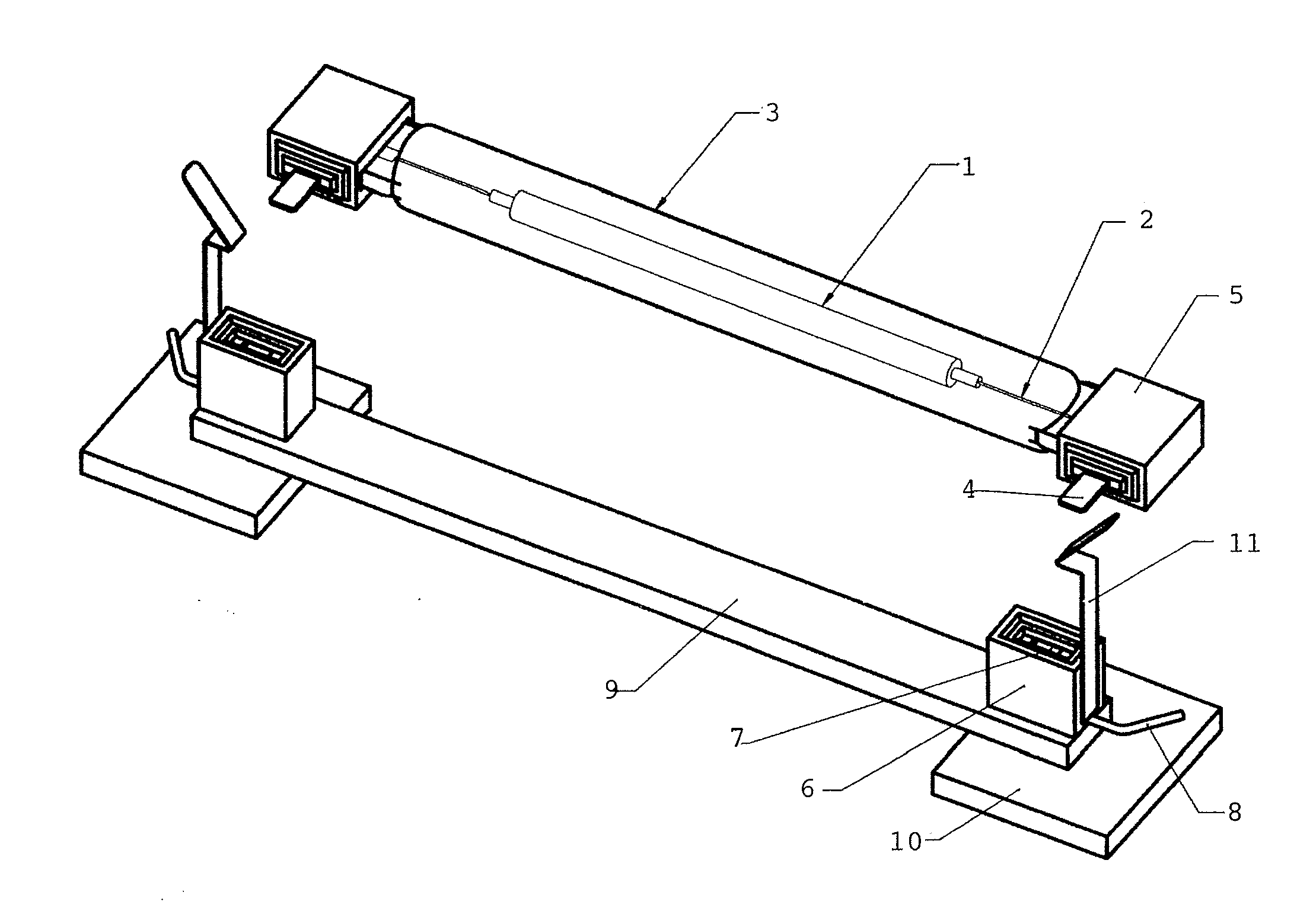
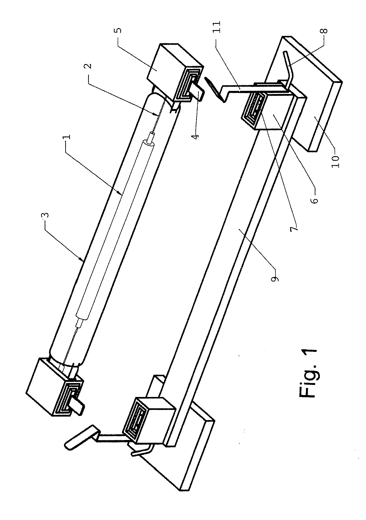
[0025]FIG. 1 shows an exemplary embodiment of a lighting device according to the invention, which can be used in greenhouses, for example.

[0026]A discharge tube 1 is situated in the interior of a tubular, light-transmitting protective tube 3. A terminal socket 5 is located at each of the two ends of the light-transmitting protective tube 3. Apart from the implementation of the terminal sockets 5, the lamp according to the invention fundamentally corresponds to the typical prior art. A flat, plate-shaped terminal tab 4 protrudes in the radial direction from each terminal socket 5 toward the protective tube 3. The terminal tabs 4 are connected via power lines 2 to the an electrode situated in the interior of discharge tube 1. Electrical contact with the opposing contact surfaces 7 ...


PUM


Abstract

A lighting device, having a tubular lamp, on each end of which a terminal socket is provided, which has a terminal for electrical contacting of the lamp, and two terminal receptacles associated with the terminal sockets, each having a metal terminal clamp for receiving one of the terminals of the terminal socket, wherein the terminal for the electrical contacting is a strip-shaped metal terminal tab and the terminal clamp has two opposing springy contact surfaces for clamping the terminal tab between them, and wherein opposing front sides of terminal socket and terminal receptacle are adapted to engage in one another in a form-fitting way in an installed state by providing a projection and a depression complementary thereto.

Description

BACKGROUND OF THE INVENTION[0001]1. Field of the Invention[0002]The invention relates to a lighting device, which is suitable above all for irradiating plants, in particular in greenhouses.[0003]2. Description of Related Art[0004]Lamps, such as discharge lamps, for greenhouses are known from the prior art, which comprise a tubular body and have an exposed lead at each end of the body to connect the lamp. For operation, these lamps are placed in special housings, which clamp the exposed leads between two spring lamellae when the housing is folded closed, and thus, produce a conductive connection.[0005]High-power lamps, for example, 1,000 Watts, are employed for use in greenhouses. It has proven to be problematic in this case that the production of a conductive connection cannot be reliably ensured. In the event of inadequate contact of the leads with the contact lamellae of the housing, because of high (ignition) voltages, which can reach approximately 3,000 V, electric arcs arise be...

Claims


Application Information

Patent Timeline
IPC IPC(8): F21V21/002
CPCH01R13/113H01R33/0827H01R33/02H01R13/642H01R13/5219
Inventor KUEHNERT, GUNNARWESSELING, HEINZ-JUERGEN
Owner BLV LICHT UND VAKUUMTECHNIK GMBH
Learn More