Touchpad with strip-shaped input area

Inactive Publication Date: 2011-11-03
IEE INT ELECTRONICS & ENG SA
View PDF1 Cites 130 Cited by
  • Summary
  • Abstract
  • Description
  • Claims
  • Application Information

AI Technical Summary

Benefits of technology

[0007]The invention provides a user-friendlier touchpad, in which the above-mentioned drawbacks are reduced or eliminated.
[0010]The touchpad according to the invention may therefore be operated in two different ways and thus unites two input devices in a single one. Different actions may result from operating the touchpad, depending on whether the user's finger or stylus touches the operating surface lightly (i.e. without causing the cover to be pressed onto the support element) or hardly (i.e. so as to cause the cover to be pressed onto the support element). Nevertheless, the present invention eliminates the need for providing separate detection electrodes for the capacitive measurement and the resistive measurement, which leads to a simplified touchpad structure and saves production costs.
[0013]The resistive trace of the touchpad may be provided as a continuous resistive strip or, alternatively, as an arrangement of serially interconnected resistive spots or patches. If the resistive trace is a continuous strip, the outputted position of the finger or stylus may vary continuously; if, however, the resistive trace comprises several resistive spots or patches, there is some quantization of the output position as a function of the true position of the finger or stylus. Preferably, the density of such serially interconnected resistive spots or patches is chosen sufficiently high to avoid jumps in the output position when the true position is continuously varied. Preferably, the detection electrodes of the cover are also arranged in such a way that the capacitive coupling between the individual detection electrodes and the user's finger or stylus also varies substantially without jumps as the finger or stylus moves continuously (e.g. at constant speed) over the operating surface.
[0024]Advantageously, the first input mode may comprise at least one of a pointing mode and a scrolling mode, and wherein the second input mode comprises at least one of a selecting mode and a drag-and-drop mode. Those skilled will appreciate that the invention is especially useful in an electronic appliance in which the touchpad and the display are separate, e.g. in a laptop computer. Indeed, when using such appliances, the operator often has to first move the cursor or visual indicator to the desired location, before he can choose another action by clicking a button or tapping. If the touchpad according to the present invention is used, the operator may move the cursor or visual indicator by lightly touching the operating surface and moving the finger thereon. When the cursor is in the desired location, the second action may be initiated by depressing the cover of the touchpad. Drag-dropping may be considerably simplified since appliance can be so configured that the operator may move a selected item to another location by keeping the cover depressed when moving his or her finger or stylus.

Problems solved by technology

The disadvantage of separate buttons is that the user needs both his or her hands to access the mouse-click functionality.
While some people have no difficulty in using the tapping functionality provided by touchpads, others deliberately switch it off (if this is possible and if they know how this can be done) and work with the associated buttons or keys because they otherwise would often unintentionally trigger the tapping functionality.

Method used


Image

  • Touchpad with strip-shaped input area
  • Touchpad with strip-shaped input area
  • Touchpad with strip-shaped input area

Examples


Embodiment Construction

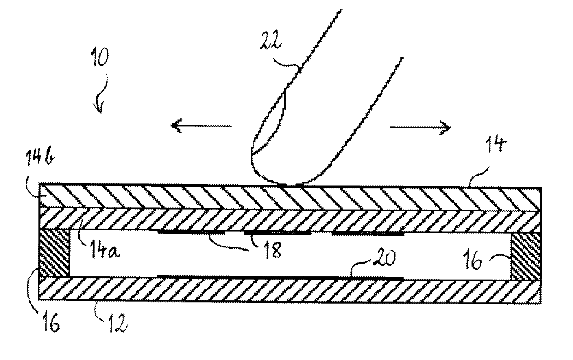
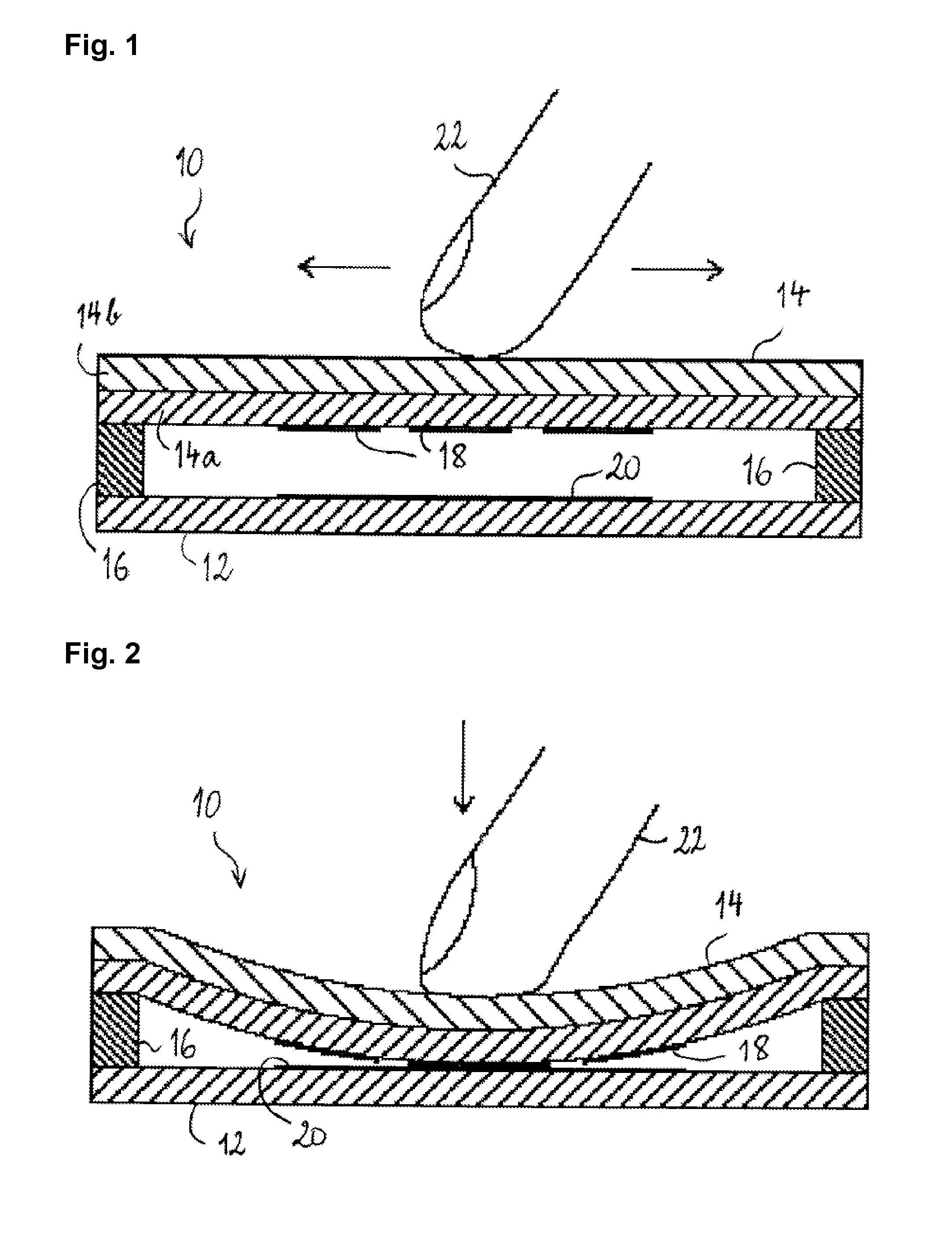
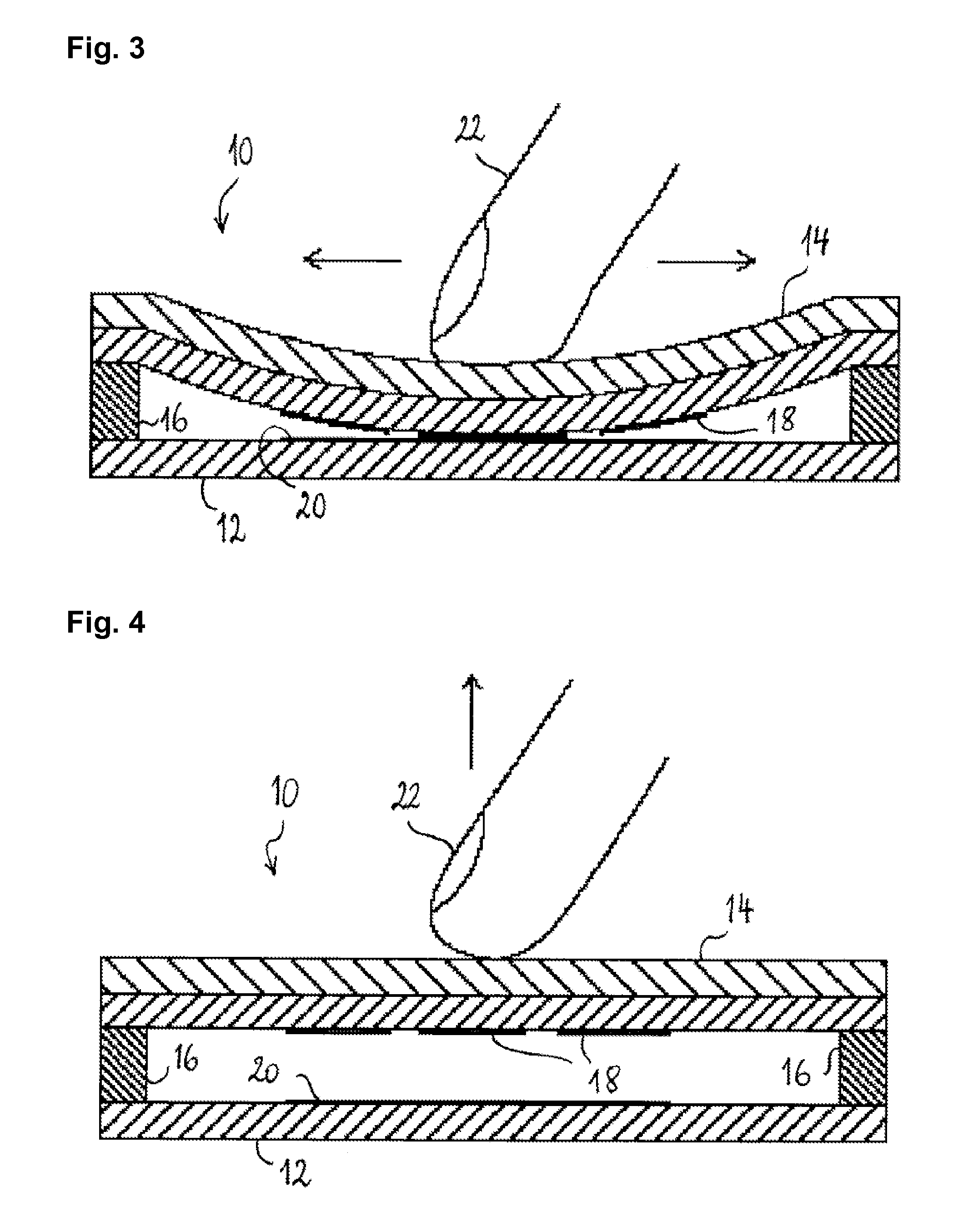
[0041]Touchpad 10 of FIGS. 1 to 4 is configured for detecting the position of a user's finger or stylus in a single dimension. The touchpad 10 has an elongated input area with a main line of extension, which defines the dimension along which the user may move his or her finger or stylus and in which the position is detected. The touchpad 10 comprises a support element 12, a cover plate 14 and a spacer 16 delimiting the input zone, in which the cover plate 14 spans over the support element 12. The support element 12 is shown here as a mechanically rigid insulating plate but those skilled will appreciate that the support element more preferably comprises a mechanically rigid base plate having an insulating substrate, such as a film or a sheet, applied on the side facing the cover plate 14. The cover plate 14 comprises an insulating substrate 14a and a protective layer 14b applied to the surface of the substrate 14a that faces toward the operator. The protective layer 14b is made of a ...


PUM


Abstract

A touchpad with an input area having a straight or curved main line of extension comprises a support element, a cover having a first surface facing away from the support element and a second surface facing towards the support element and one or more spacers arranged at a periphery of the input area. The one or more spacers mount the cover on the support element in such a way that the cover spans over the support plate in the input area while it is depressible towards the support element by a force acting on the input area of the touchpad. A resistive trace is so arranged on the support element that it extends along the main line of extension of the input area. At least one terminal contacts the resistive trace at a particular point of the main line of extension of the input area and a set of detection electrodes is arranged on the second surface of the cover in facing relationship with the resistive trace. The detection electrodes are configured and arranged for capacitively detecting a position of a user's finger or stylus when the user's finger or stylus is in proximity of or in light touch with the first surface of the cover, and for resistively detecting a position of a user's finger or stylus when the user's finger or stylus depresses the cover and so brings at least one of the detection electrodes into electrical contact with the resistive trace.

Description

TECHNICAL FIELD[0001]The present invention generally relates to a touchpad having a strip-shaped input area, i.e. an input area having a straight or curved main line of extension whose width orthogonal to this main line of extension is comparably small.BACKGROUND[0002]Input devices, in particular capacitive input devices, with strip-shaped input areas are well known in the technical field, e.g. from document U.S. Pat. No. 4,264,903. The latter discloses a strip-shaped capacitive touchpad, comprising a solid panel having a front surface facing an operator of the touchpad and a rear surface facing away from the operator, a plurality of detection electrodes disposed along a predefined geometric curve (e.g. a straight line or an annular curve) and applied to the rear surface of the panel. The emplacement of the operator's finger on the front surface of the panel at a point upon the detection electrode pattern causes an additional capacitance between a pair of adjacent detection electrod...

Claims


Application Information

Patent Timeline
IPC IPC(8): G06F3/044G06F3/045
CPCH03K17/9622G06F3/03547
Inventor SERBAN, BOGDANBOYER, PHILIPPEHOYER, DAVID
Owner IEE INT ELECTRONICS & ENG SA
Why Eureka
Try Eureka