
Binaural rendering of a multi-channel audio signal

a multi-channel audio and audio signal technology, applied in the field ofbinaural rendering of multi-channel audio signals, can solve the problems of not meeting the requirements of many applications, mpeg surround, and upcoming applications that pose further demands on audio coding algorithms, and achieve the effects of reducing the amount of degrading, reducing the number of decorrelations or synthetic signal processing, and improving quality

Active Publication Date: 2011-10-27
DOLBY INT AB +2
View PDF6 Cites 136 Cited by
  • Summary
  • Abstract
  • Description
  • Claims
  • Application Information

AI Technical Summary

Benefits of technology

[0014]One of the basic ideas underlying the present invention is that starting binaural rendering of a multi-channel audio signal from a stereo downmix signal is advantageous over starting binaural rendering of the multi-channel audio signal from a mono downmix signal thereof in that, due to the fact that few objects are present in the individual channels of the stereo downmix signal, the amount of decorrelation between the individual audio signals is better preserved, and in that the possibility to choose between the two channels of the stereo downmix signal at the encoder side enables that the correlation properties between audio signals in different downmix channels is partially preserved. In other words, due to the encoder downmix, the inter-object coherences are degraded which has to be accounted for at the decoding side where the inter-channel coherence of the binaural output signal is an important measure for the perception of virtual sound source width, but using stereo downmix instead of mono downmix reduces the amount of degrading so that the restoration / generation of the proper amount of inter-channel coherence by binaural rendering the stereo downmix signal achieves better quality.
[0015]A further main idea of the present application is that the afore-mentioned ICC (ICC=inter-channel coherence) control may be achieved by means of a decorrelated signal forming a perceptual equivalent to a mono downmix of the downmix channels of the stereo downmix signal with, however, being decorrelated to the mono downmix. Thus, while the use of a stereo downmix signal instead of a mono downmix signal preserves some of the correlation properties of the plurality of audio signals, which would have been lost when using a mono downmix signal, the binaural rendering may be based on a decorrelated signal being representative for both, the first and the second downmix channel, thereby reducing the number of decorrelations or synthetic signal processing compared to separately decorrelating each stereo downmix channel.

Problems solved by technology

However, upcoming applications pose further demands on audio coding algorithms.
However, MPEG Surround, unfortunately, does not fulfill all requirements posed by many applications.
The absence of the effect of the acoustical pathway from sources at certain physical positions to the eardrums causes the spatial image to sound unnatural since the cues that determine the perceived azimuth, elevation and distance of a sound source are essentially missing or very inaccurate.
Even worse: the thus obtained binaural output signal would have a poor audio quality due to the fact that in order to achieve the virtual loudspeaker signals, a relatively large amount of synthetic decorrelation signals would have to be mixed into the upmixed signals in order to compensate for the correlation between originally uncorrelated audio input signals, the correlation resulting from downmixing the plurality of audio input signals into the downmix signal.
Unfortunately, mono downmix necessitates all audio signals to be mixed into one common mono downmix signal so that the original correlation properties between the original audio signals are maximally lost and therefore, the rendering quality of the binaural rendering output signal is non-optimal.

Method used


Image

  • Binaural rendering of a multi-channel audio signal
  • Binaural rendering of a multi-channel audio signal
  • Binaural rendering of a multi-channel audio signal

Examples


Embodiment Construction

[0023]Before embodiments of the present invention are described in more detail below, the SAOC codec and the SAOC parameters transmitted in an SAOC bit stream are presented in order to ease the understanding of the specific embodiments outlined in further detail below.

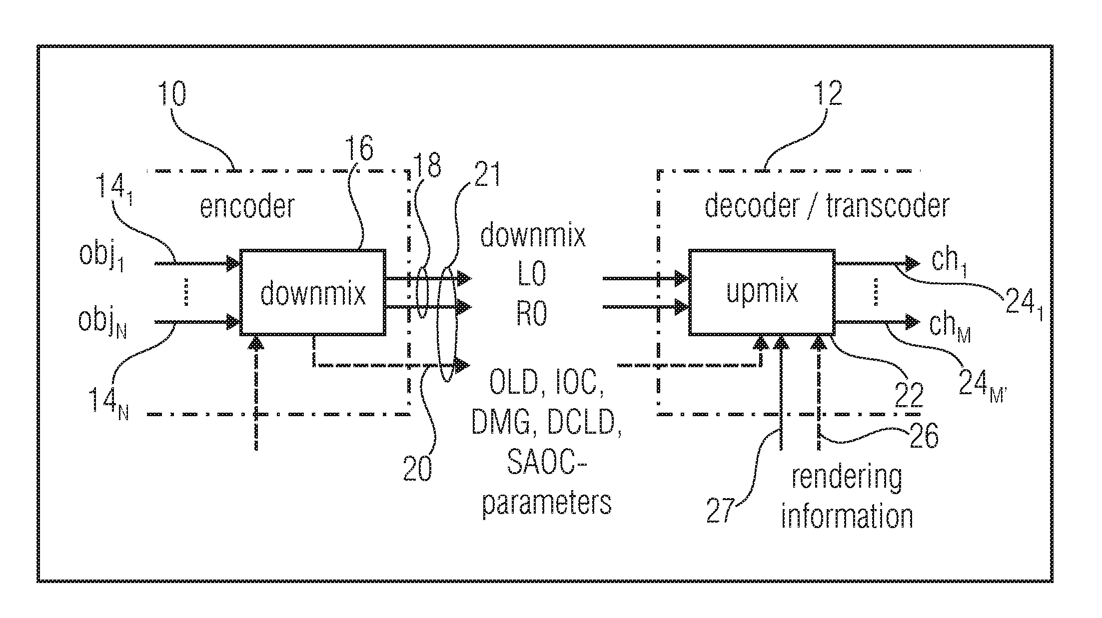
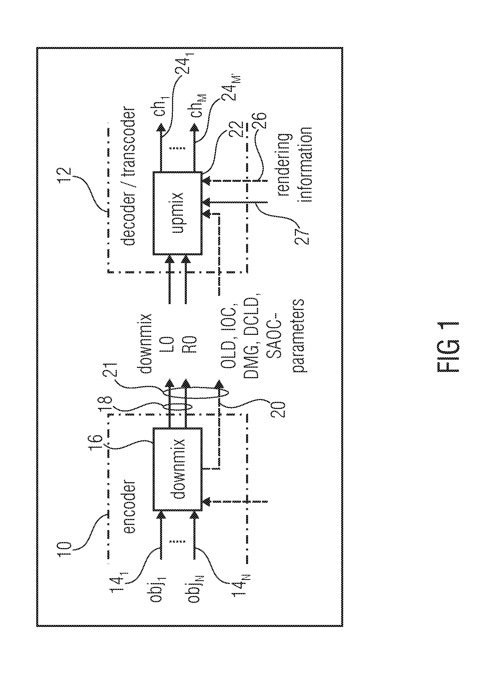
[0024]FIG. 1 shows a general arrangement of an SAOC encoder 10 and an SAOC decoder 12. The SAOC encoder 10 receives as an input N objects, i.e., audio signals 141 to 14N. In particular, the encoder 10 comprises a downmixer 16 which receives the audio signals 141 to 14N and downmixes same to a downmix signal 18. In FIG. 1, the downmix signal is exemplarily shown as a stereo downmix signal. However, the encoder 10 and decoder 12 may be able to operate in a mono mode as well in which case the downmix signal would be a mono downmix signal. The following description, however, concentrates on the stereo downmix case. The channels of the stereo downmix signal 18 are denoted LO and RO.

[0025]In order to enable the SAOC decoder ...


PUM


Abstract

Binaural rendering a multi-channel audio signal into a binaural output signal is described. The multi-channel audio signal has a stereo downmix signal into which a plurality of audio signals are downmixed, and side information having a downmix information, as well as object level information of the plurality of audio signals and inter-object cross correlation information. Based on a first rendering prescription, a preliminary binaural signal is computed from the first and second channels of the stereo downmix signal. A decorrelated signal is generated as an perceptual equivalent to a mono downmix of the first and second channels of the stereo downmix signal being, however, decorrelated to the mono downmix. Depending on a second rendering prescription, a corrective binaural signal is computed from the decorrelated signal and the preliminary binaural signal is mixed with the corrective binaural signal to obtain the binaural output signal.

Description

CROSS-REFERENCE TO RELATED APPLICATIONS[0001]This application is a continuation of copending International Application No. PCT / EP2009 / 006955, filed Sep. 25, 2009, which is incorporated herein by reference in its entirety, and additionally claims priority from European Application No. EP 09006598.8, filed May 15, 2009 and U.S. Provisional Application No. 61 / 103,303, filed Oct. 7, 2008, which are all incorporated herein by reference in their entirety.BACKGROUND OF THE INVENTION[0002]The present application relates to binaural rendering of a multi-channel audio signal.[0003]Many audio encoding algorithms have been proposed in order to effectively encode or compress audio data of one channel, i.e., mono audio signals. Using psychoacoustics, audio samples are appropriately scaled, quantized or even set to zero in order to remove irrelevancy from, for example, the PCM coded audio signal. Redundancy removal is also performed.[0004]As a further step, the similarity between the left and righ...

Claims


Application Information

Patent Timeline
Patent Type & Authority Applications(United States)
IPC IPC(8): G10L19/00G10L19/008
CPCG10L19/008G10L19/20H04S1/005H04S2420/03H04S2400/01H04S2420/01H04S3/004H04S3/00H04S1/00
Inventor KOPPENS, JEROENMUNDT, HARALDTERENTIEV, LEONIDFALCH, CORNELIAHILPERT, JOHANNESHELLMUTH, OLIVERVILLEMOES, LARSPLOGSTIES, JANBREEBAART, JEROENENGDEGARD, JONAS
Owner DOLBY INT AB
Learn More