
Smart control device

Active Publication Date: 2011-10-27
LG ELECTRONICS INC
View PDF27 Cites 108 Cited by
  • Summary
  • Abstract
  • Description
  • Claims
  • Application Information

AI Technical Summary

Benefits of technology

[0013]Another object of the present invention is to provide a smart control device that can be equipped in an electrical appliance (or device), so as to be capable of controlling the electrical appliance by using diverse information that is provided from both the inside and the outside of the electrical appliance.
[0023]When the energy saving operation mode of the electrical appliance is maintained, the smart controller may control the electrical appliance so that a current operation mode can be maintained, when the variation level of the status information or the environment information is below a first variation reference value, may control the electrical appliance so that the operation mode can be changed in order to restrain a change in the status information or the environment information within a range of the energy saving operation mode, when the variation level of the status information or the environment information is above the first variation reference value and below a second variation reference value, and may control the electrical appliance so that the energy saving operation mode can be cancelled in order to restrain a change in the status information or the environment information, and so that the electrical appliance can be operated in a general operation mode, when the variation level of the status information or the environment information is above the second variation reference value.

Problems solved by technology

Furthermore, since the pricing system was actually a fixed pricing system, there was a problem in that inducements, such as incentive, could not be promoted to the consumers in accordance with the changes in the electricity price.

Method used


Image

  • Smart control device
  • Smart control device
  • Smart control device

Examples


Embodiment Construction

[0049]Reference will now be made in detail to the preferred embodiments of the present invention, examples of which are illustrated in the accompanying drawings. Wherever possible, the same reference numbers will be used throughout the drawings to refer to the same or like parts.

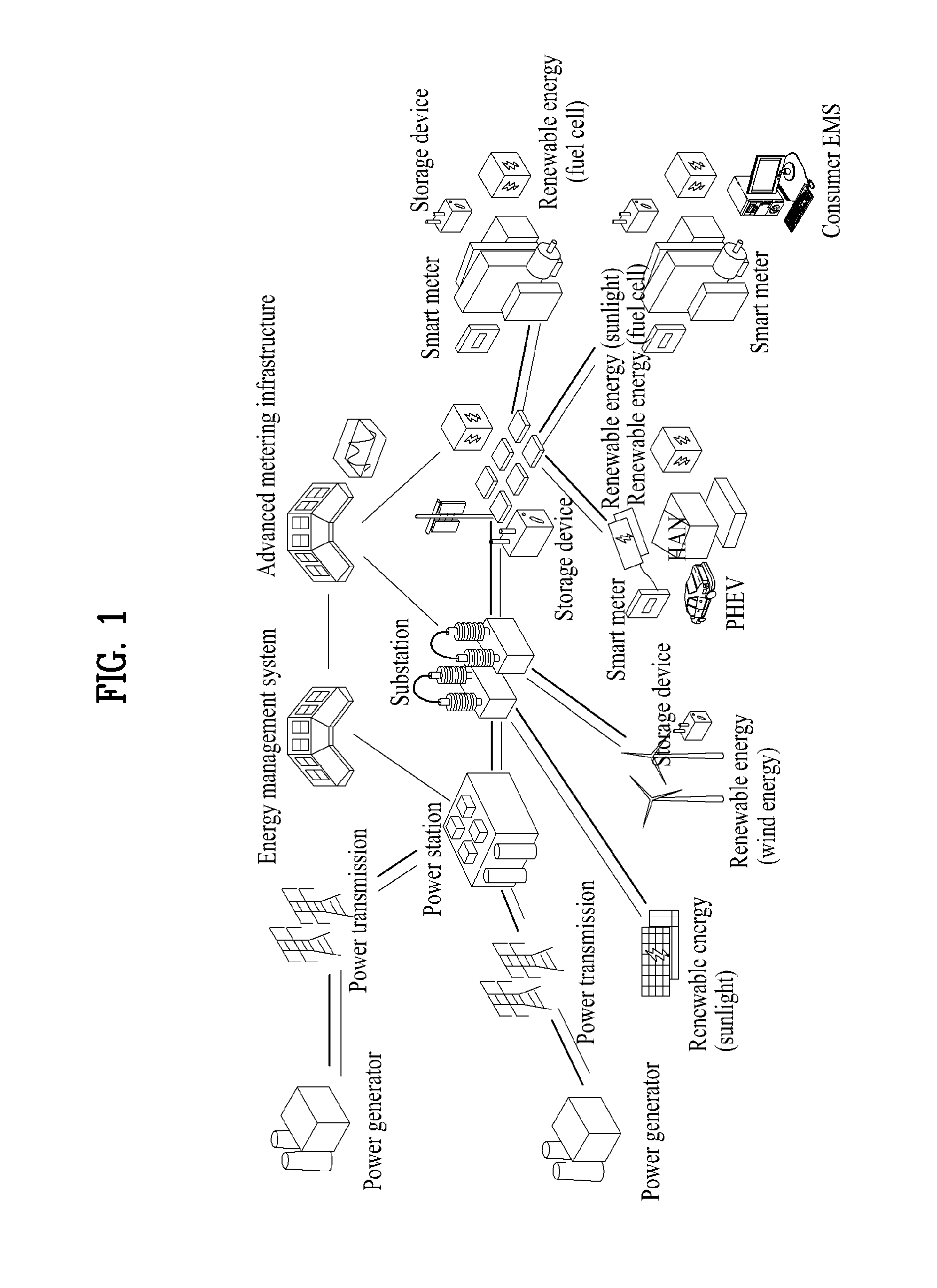
[0050]FIG. 1 illustrates a general view of a smart grid that is realized in the present invention. Herein, a smart grid includes a power generator, which generates power via thermal power generation, nuclear power generation, or hydroelectric power generation, and a solar energy generator and a wind energy generator, which use renewable energy such as solar energy and wind energy.

[0051]Also, a thermal power generator, a nuclear power generator, or a hydroelectric power generator sends the generated power to a power station through a transmission line. Then, the power station sends the generated power (or electricity) to substations so that the electricity can be distributed to a party demanding electric powe...


PUM


Abstract

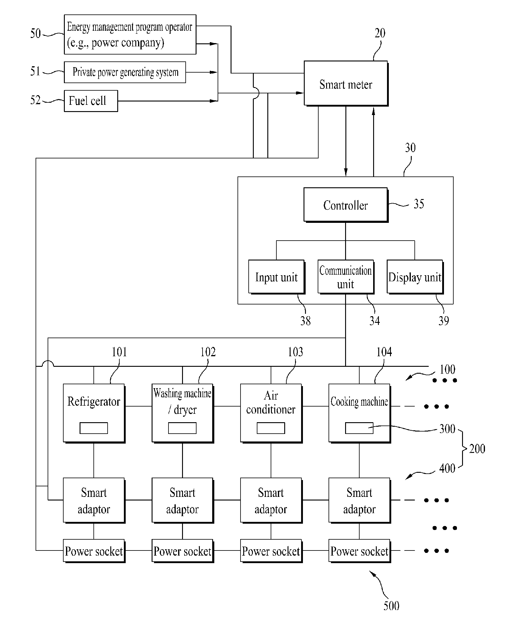
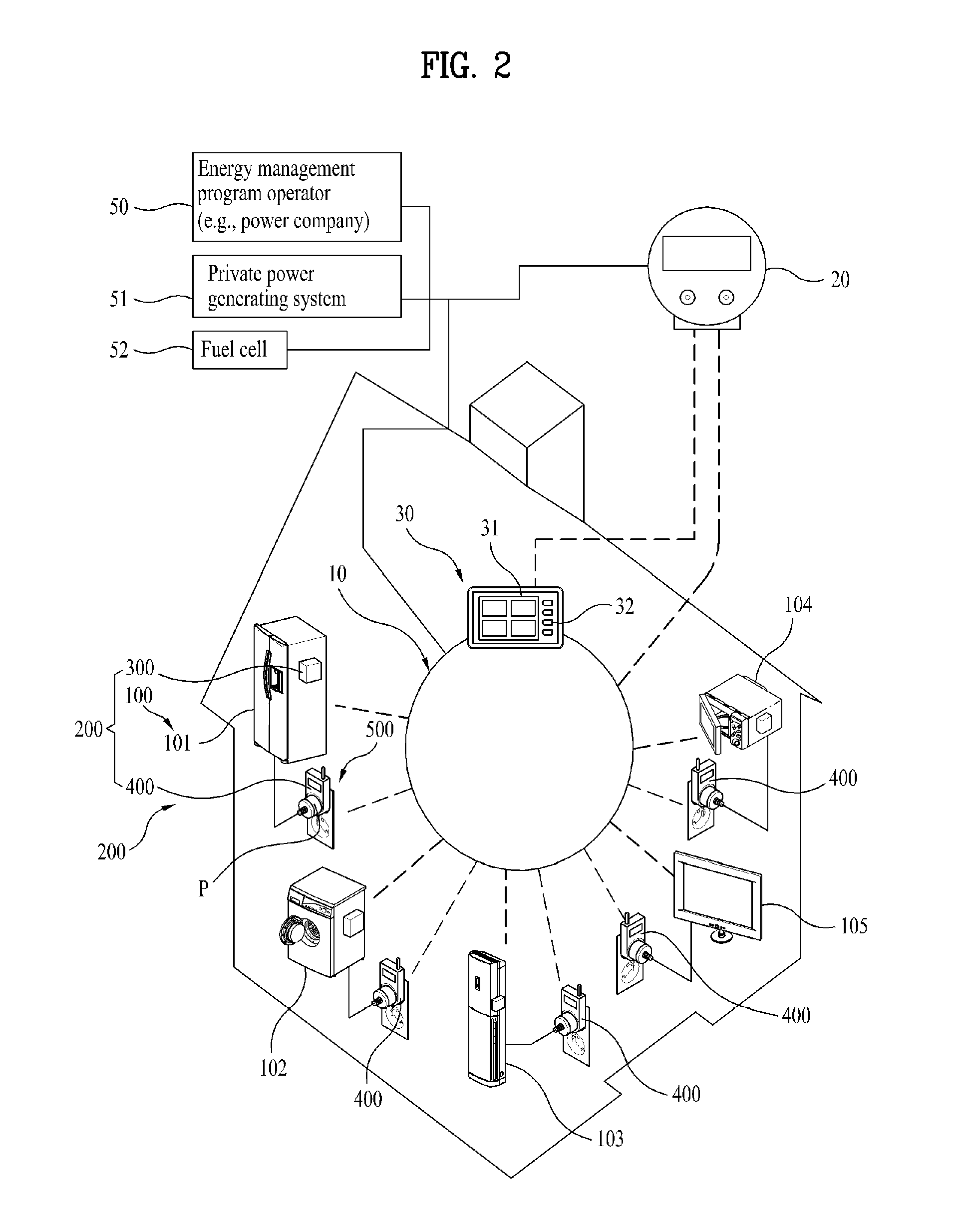
A smart control device is disclosed. The smart control device can be equipped in an electrical appliance, so as to be capable of controlling the electrical appliance by using diverse information that is provided from both the inside and the outside of the electrical appliance. In a smart control device monitoring and scheduling operations of an electrical appliance, the smart control device includes an interface unit configured to receive energy information, a smart controller configured to control energy saving functions of the electrical appliance based upon the energy information received from the interface unit, and an input unit configured to receive an inputted control command respective to the electrical appliance. Herein, the smart controller may be provided in the electrical appliance, and the smart controller may control the electrical appliance so that the electrical appliance can be operated in an energy saving operation mode based upon the received energy information.

Description

[0001]Pursuant to 35 U.S.C. § 119(a), this application claims the benefit of the Korean Patent Application No. 10-2010-0038957, filed on Apr. 27, 2010, which is hereby incorporated by reference as if fully set forth herein.BACKGROUND OF THE INVENTION[0002]1. Field of the Invention[0003]The present invention relates to a smart control device and, more particularly, to a smart control device that is provided in electrical devices (or appliances). Herein, the smart control device can receive and transmit diverse information that are provided inside or outside of the corresponding electrical device, and the smart control device can also control the corresponding electrical device based upon the received and / or transmitted information.[0004]2. Discussion of the Related Art[0005]Energy (or power) that is used to operate electrical appliances that are used in households and office equipments that are used in offices is generally provided in the order of a power generator, which is operated...

Claims


Application Information

Patent Timeline
IPC IPC(8): G06F1/32
CPCG06Q10/00Y04S20/242H02J3/14H02J9/005H02J2003/143H04L12/12H04L12/282H04L2012/285Y02B60/34Y02B70/3225Y02B70/3233Y02B70/325Y02B70/3266Y02B60/32Y04S20/222Y04S20/225Y04S20/228G06Q50/06H02J2310/14Y02B70/30Y02D30/50Y04S20/20H04L12/16H04L12/28
Inventor PARK, JONG SOO
Owner LG ELECTRONICS INC
Learn More