
Device for a winch-operated wave-power plant

a technology of wave power plant and winch, which is applied in the direction of machine/engine, engine components, sea energy generation, etc., can solve the problems of unreasonably large design cost and lack of necessary characteristics

Inactive Publication Date: 2011-10-27
STRAUMEKRAFT
View PDF1 Cites 7 Cited by
  • Summary
  • Abstract
  • Description
  • Claims
  • Application Information

AI Technical Summary

Benefits of technology

[0018]To execute this principle in practice, the invention described herein comprises a slip clutch 6 between the winch 2 and the outgoing axle 8 from the mechanical energy absorption- and conversion system 10. In one embodiment this slip clutch is engaged and disengaged by built-in electromagnets governed by a computer. The computer is programmed to disengage the slip clutch when the amount of energy pe...

Problems solved by technology

But these lack the necessary characteristics in order for a wave-power plant, without incurring unreasonably large design costs, to be capable of surviving the encounter with the at times extreme forces of the ocean waves in the event of storms and hurricanes.

Method used


Image

  • Device for a winch-operated wave-power plant
  • Device for a winch-operated wave-power plant

Examples


Embodiment Construction

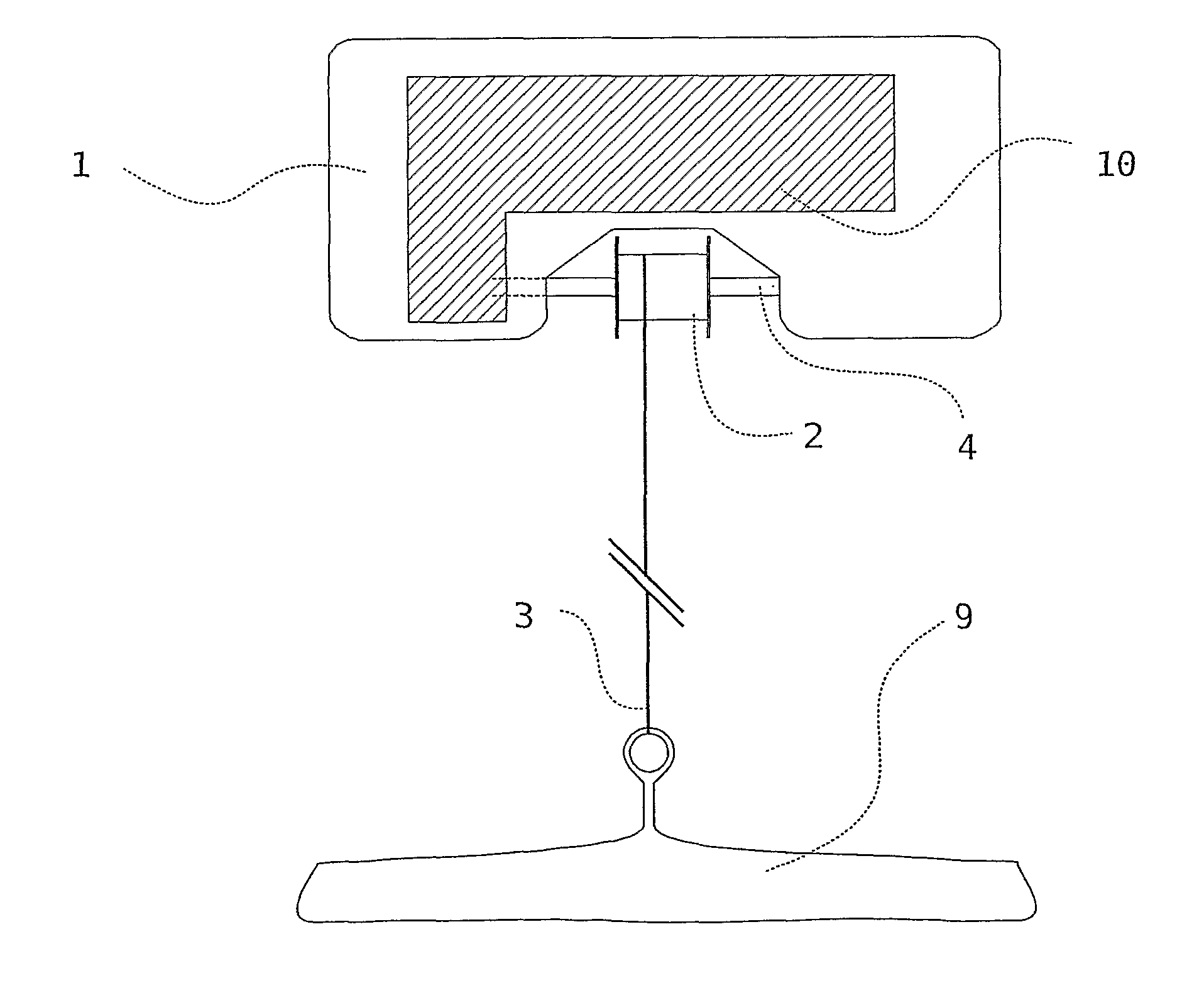
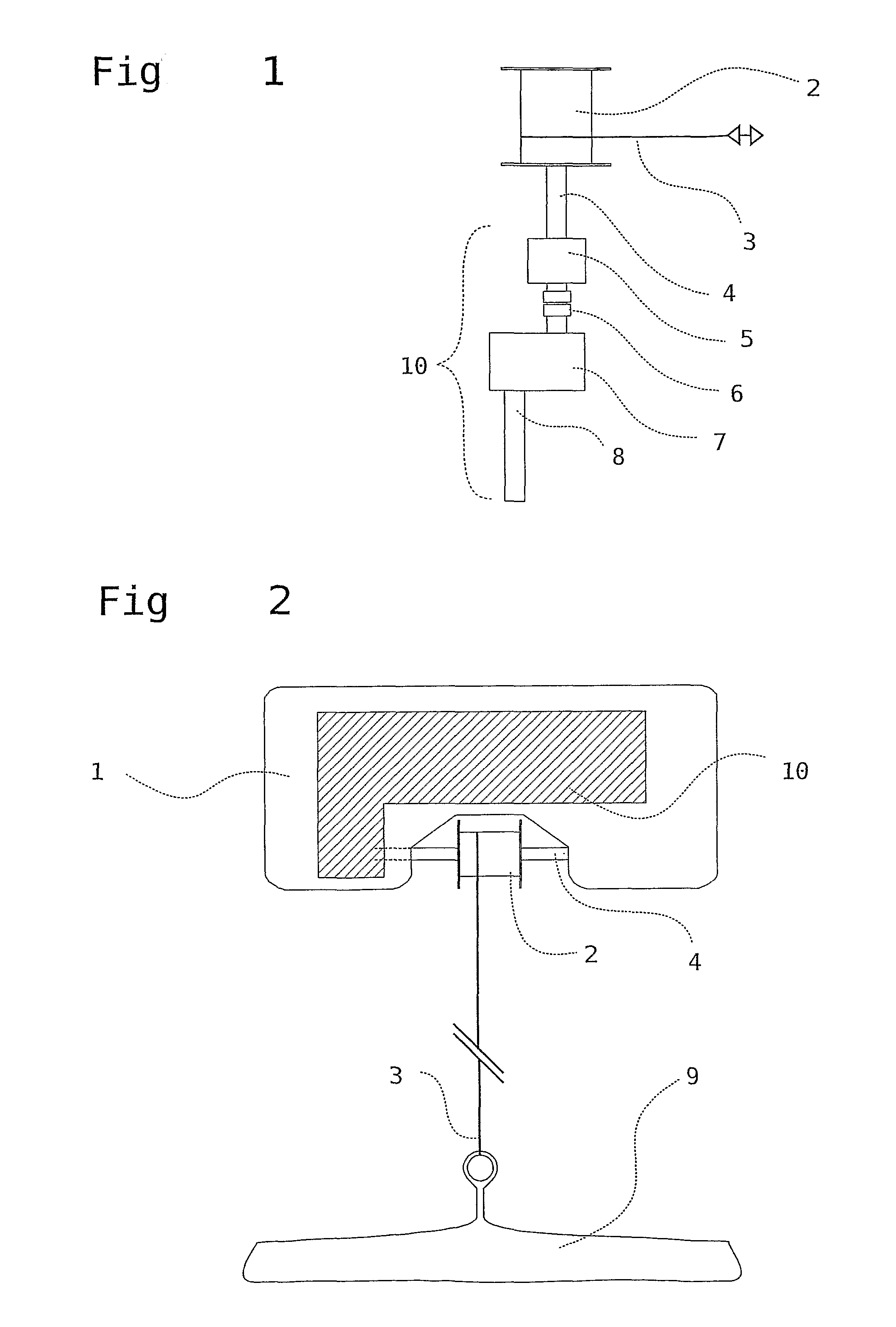
[0023]The device according to the invention comprises a wave energy absorbing floating buoy with energy absorption- and conversion system, which may be placed inside the buoy, on the sea floor or elsewhere. FIGS. 1 and 2 illustrate the principle of the device according to the invention. A floating buoy 1 acts as absorption element. This buoy is connected to a winch 2 with a winch wire 3. The buoy 1 and the winch 2 with the winch wire 3 are connected in such a manner that the winch is forced to rotate when the wave forces move the buoy 1 in the winch wire's longitudinal direction. The winch and the winch wire interconnect the buoy and a reference body below the waves of the ocean surface. This reference body may be a pelagic anchor plate, an anchor 9 at the seabed as shown in FIG. 2, an expansion bolt in the rock of the seabed, or a different anchoring device. In the embodiment shown in FIG. 2, the winch and the energy absorption- and conversion system is in the buoy. But those eleme...


PUM


Abstract

A device for a winch-operated wave-power plant with a self-tightening winch connecting a wave-energy-absorbing body via a winch wire to a reference point. A winch cable drum is connected via a mechanical energy absorption- and conversion system to a rotating outgoing axle. The mechanical energy absorption- and conversion system is connected to a slip clutch. The slip clutch is arranged between the winch axle and the outgoing axle. The slip clutch can be set to slip, thereby reducing the flow of mechanical rotational energy from the rotating winch through the mechanical energy absorption- and conversion system, so that the amount of energy per time unit absorbed by the mechanical energy absorption- and conversion system is limited by how much the slip clutch slips. The system further includes a governing system controlling the slip clutch by acting upon excessive speed and / or forces in the winch and the winch axle.

Description

BACKGROUND OF THE INVENTION[0001]In the patent literature over 1000 devices are described for converting the energy of ocean-waves into useful energy. Several wave-energy concepts, based on different technological approaches, have been presented. What has not been appreciated in these earlier concepts is that a successful commercial exploitation of energy from ocean waves requires the plants to have one (or more) inherent or ancillary overload protection mechanism(s). To become economically viable, the plants have to have some strategy for tackling the encounter with the most extreme waves. In essence the plants must interact differently with extreme waves than with average size and smaller waves. In average size and smaller waves, a plant should try to absorb as much energy as possible from the waves, to maximize its energy production. But in an extreme wave, it should behave differently to avoid absorbing the excessive energy from that wave, because that energy could damage the pl...

Claims


Application Information

Patent Timeline
IPC IPC(8): F03B13/18
CPCY02E10/38F03B13/1865Y02E10/30
Inventor STRAUME, INGVALDSTRAUME, SIVERT
Owner STRAUMEKRAFT
Learn More