Eureka AIR delivers breakthrough ideas for toughest innovation challenges, trusted by R&D personnel around the world.

Diiva, displayport, dvi, usb, and HDMI diy field termination products

a technology of diy field termination and dvi, which is applied in the direction of insulated conductors, coupling device connections, cables, etc., can solve the problems of poor electrical performance and appearance, failure to file termination, and difficulty in adding (i.e. terminating) a male connector (i.e. plugging) onto a standard hdmi or other format cable in the field

Inactive Publication Date: 2011-10-20
LUXI ELECTRONICS CORP
View PDF6 Cites 61 Cited by
  • Summary
  • Abstract
  • Description
  • Claims
  • Application Information

AI Technical Summary

Benefits of technology

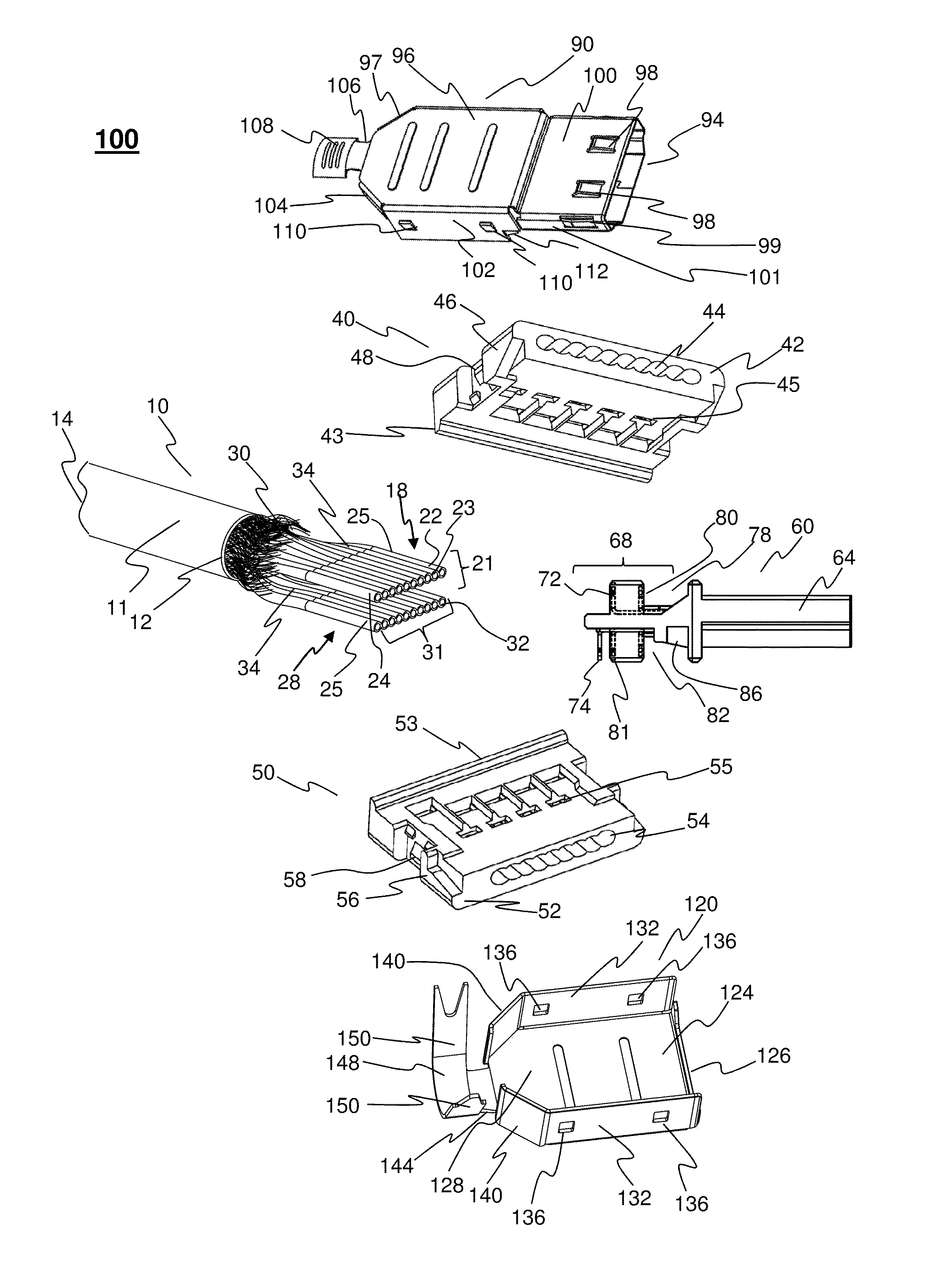
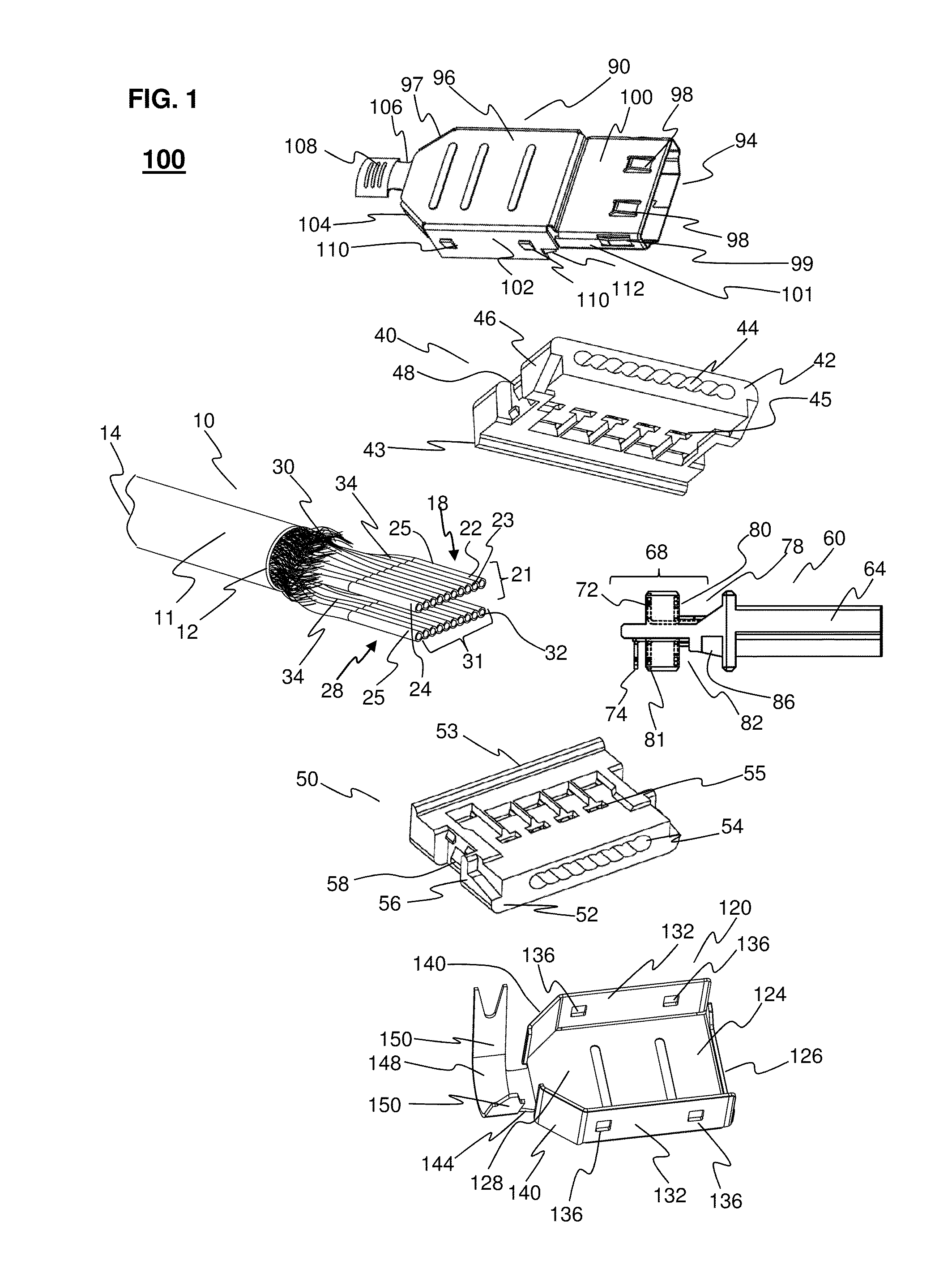
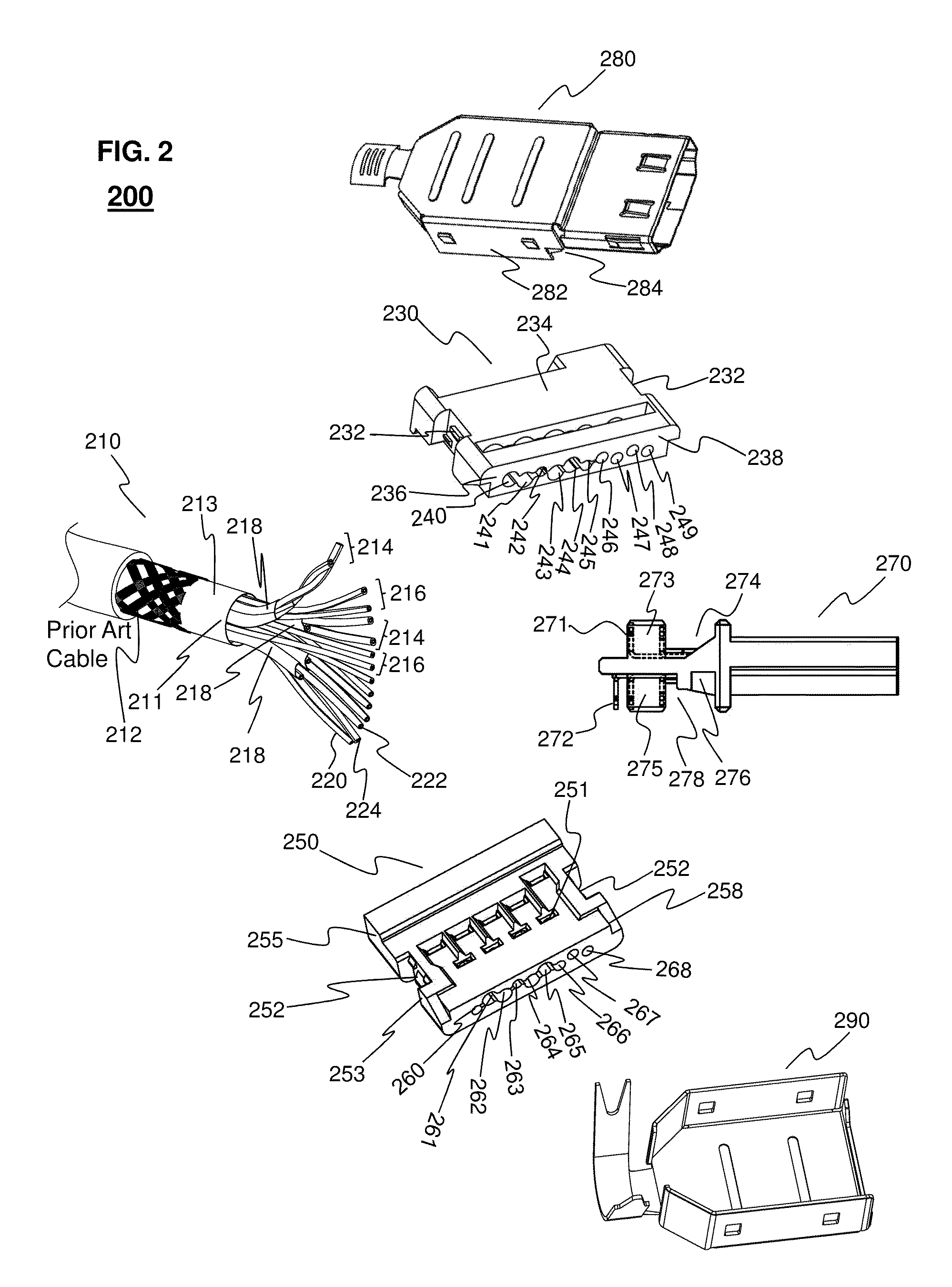
Embodiments include a digital video audio DIY (Do It Yourself) filed termination connector including a shell configured for encasing a connector core and wire holder subunit. In some embodiments the shell further comprises an inner shell and outer shell. The connector core is inserted locking into the shell either into a top shell and bottom shell pair or into a single shell (e.g. rubber boot or sleeve). A connector core configured with a plurality of pins is positioned to receive a plurality of wires from at least one or more wire holders. The connector core contains at least one or more flexible buckles. Each of the flexible buckles have at least one or more hook protrusion that is angled for locking with at least one clip, similarly angled, on the wire holder. The wire holder is inserted into the connector core forming the connector core and wire holder subunit where a connection is made between the plurality of pins of the connector core and the plurality of wires in the wire holder. Each of the wire holders is configured with at least one clip angled for locking with the hook protrusion on each flexible buckle on the connector core. Each wire holder is also configured to receive and hold the plurality of wires for connecting to the plurality of pins in the connector core. In some embodiments the hook protrusion on each flexible buckle is configured at an angle of about 90 degrees, or less, and is for non-reversible mating with at least one clip a wire holder, similarly configured (i.e. at a sharp angle).
In other embodiments the top shell has a male plug member and open base with an extended portion serving as strain relief tabs. The top shell includes at least one tab for securing a connector core subunit within the base of the top shell by mating with at least one cognate receptacle on a connector core. The HDMI connector assembly system also includes a bottom shell that includes an open compartment base which is for mating with and encasing the top shell and the connector core subunit forming a connector assembly. The HDMI connector system further includes an insulating connector core that includes a first plug end for inserting within the top shell male plug member and is for contacting a female receptacle. The connector core also includes a second wire terminal end with an open body for receiving a cable and both a top and a bottom wire holder. The open body of the connector core contains an upper and lower set of flexible buckles each with a hook protrusion. Each of the hook protrusions is configured at an angle of less than 90 degrees and is for non-reversible mating with cognate clip receptacles positioned on the top and bottom wire holders. When the top and bottom wire holders are inserted into the top and bottom compartment of the connector core each of the flexible buckles can slip over the clips on the wire holders until the hook protrusion and clip receptacle are non-reversibly mated effectively locking the wire holders into the connector core as a subunit. The connector core also includes a set of top and bottom terminal pins that are positioned in the connector core for contacting wires in the wire holders. The sets of terminal pins contact the wires when the wire holders are compr

Problems solved by technology

One major problem is the difficulty of adding (i.e. terminating) a male connector (i.e. plug) onto a standard HDMI or other format cables in the field.
Since the factory pre-terminated cables only come in several fixed lengths, the extra cable would have to be coiled up in the rack resulting in poor electrical performance and appearance.
If one plug is damaged then the wall has to be knocked open to replace the entire cable.
Though solder free field termination connectors have been commercialized none has been successful for filed termination since they include short comings that affect durability and signal quality of the connectors.
For example, no current solderless connector components are sufficiently interlocking for field termination applications resulting in reversibility of the components and loosening of the connection over time.
In some cases factory machine heat sealing is employed to secure connector components together and within shells which is impractical in the field.
Further some of these connectors have thin plastic walls in the internal wire holders which crack under typical field pressure or temperature changes resulting in loosening or complete loss of connection over time.
To date there are no overall metal shells which results in poor signal grounding and shielding.
Also lack of an overall metal shells results in the front probe of the HDMI or other connector being easily snapped off the HDMI or other connector body under normal use.
One problem that has escaped workable a solution is that HDMI male connectors are somewhat loose when mated to their female receptacles and often are disconnected inadvertently causing field calls to correct disconnects from angry customers.
These problems are made worse by tight spaces common in installations like the space between the flat panel HDTV and the wall, coupled to tilting and panning features on flat panel HDTV wall mounts.
Though the HDMI specifications include square holes present on the bottom of the male probe that connect with friction springs in the female receptacle shell these are inadequate.
The HDMI specifications optional friction hole and spring combination is designed primarily for the grounding of connections and fails to correct the common disconnect problems since they do not generate sufficient restraining force to adequately keep the male connector in place.
Attempts to fix this problem include adding a thumb screw that requires the female connectors to have the compatible screw threads or active release button lock that requires one to squeeze the male connector body to open a lock tab; however these are cumbersome and have not been adopted due to their short comings.
Current methods for termination of soldering or crimping 19-pins for Type A HDMI (or for other HDMI Types: A, B, C, D, and E) cable connectors are difficult to accomplish in the field but are also is labor intensive resulting in reduced productivity and reliability.
These methods are equally difficult for field terminating DiiVA, DisplayPort, mDP, DVI, and even USB cables.
Though various flat cables are commercially available most of these suffer draw backs.
For example flat cables pose problems for pulling through conduit and often hang up due to their flat configuration.
On the other hand the HDMI cable or other cable format factories also face the need to increase the productivities for cable termination while the current methods involve separating 19 wires (or more), preparing them one by one for soldering or crimping and thus these methods are labor intensive and low in productivity.

Method used


Image

  • Diiva, displayport, dvi, usb, and HDMI diy field termination products
  • Diiva, displayport, dvi, usb, and HDMI diy field termination products
  • Diiva, displayport, dvi, usb, and HDMI diy field termination products

Examples


first embodiment

In specific embodiments the retention spring parameters of the length and width of the second member and third member and first and second angle are set. In a first embodiment the retention spring has a second member with a length of about 0.8 mm to about 1.1 mm and width of about 0.8 mm to about 1.0 mm. In this embodiment the third member has a length of about 2.0 mm to about 2.4 mm and a width of about 0.8 mm to about 1.2 mm. The first angle of this embodiment is set at about 7.1 degrees to about 10.1 degrees and the second angle is set at about 2.9 degrees to about 4.9 degrees.

second embodiment

In a second embodiment the retention spring has a second member with a length of about 1.1 mm to about 1.5 mm and width of about 1.0 mm to about 1.3 mm. In this embodiment the third member has a length of about 2.7 mm to about to about 3.0 mm and a width of about 0.6 mm to about 1.0 mm. The first angle of this embodiment is set at about 5.4 degrees to about 8.6 degrees and the second angle is set at about 2.2 degrees to about 3.2 degrees.

third embodiment

In a third embodiment the retention spring has a second member with a length of about 1.1 mm to about 1.5 mm and width of about 0.9 to about 1.2 mm. In this embodiment the third member has a length of about 1.5 mm to about 2.0 mm and a width of about 1.2 mm to about 1.4 mm. The first angle of this embodiment is set at about 11.3 degrees to about 14.3 degrees and the second angle is set at about 11.3 degrees to about 14.3 degrees.


PUM


Abstract

The invention provides a system of components, methods for assembly, and a hand tool, for adding a HDMI (i.e. All HDMI Types: A, B, C, D, and E), DiiVA, DisplayPort, Mini DisplayPort, DVI, and USB (i.e. all USB Types, A, B, mini-A, mini-B, micro-A, and micro-B) connector to standard and modified ribbon cables for field termination or factory installation. Features of the connector system including the locking top shell, bottom shell, single shell, wire holders and the connector core all make possible and efficient the addition of a solderless male connector. The invention also provides a locking plug which can mate with female connectors with great retaining force. Features of the modified ribbon type cable facilitate threading of the wire holders significantly improving the time it takes to assemble a male connector on the cable. The hand tool disclosed is designed to accomplish all steps of assembly for field termination.

Description

FIELD OF THE INVENTIONThe invention relates to a system of components and methods for making digital format DIY connectors for field termination and factory termination for audio and visual signal transmission, switching and distribution. Included are connector components including insulated connector core units, wire holders, top shells, and bottom shells as well as modified cables, wire holders, specialized hand tools, and methods for field termination assembly, and a locking plug design.BACKGROUNDThe development of advanced electronic devices that demand improved signal transmission has increased the need for custom installations of high definition multimedia interface (HDMI) video audio connections in the field. Other installations include DiiVA, DisplayPort, Mini DisplayPort (mDP), DVI, and USB formats. One major problem is the difficulty of adding (i.e. terminating) a male connector (i.e. plug) onto a standard HDMI or other format cables in the field. Many installers prefer or...

Claims


Application Information

Patent Timeline
IPC IPC(8): H01R13/58
CPCH01B7/0892H01R9/035H01R12/616H01R13/504H01R12/594H01R13/6592H01R43/015H01R2107/00H01R13/506H01R13/65915
Inventor LU, XIAOZHENGHU, SENHUA
Owner LUXI ELECTRONICS CORP
Why Eureka
Eureka Blog
Learn More