
Articulated object regionarticulated object region detection apparatus and method of the same

a detection apparatus and a technology for articulating objects, applied in the field of detecting moving objects, can solve the problems of inability to accurately extract moving objects, inability to accurately apply the model obtained by parameterizing moving objects to difficulty in appropriately extracting the candidate for the moving object region, etc., to achieve accurate detection of moving objects

Active Publication Date: 2011-10-20
PANASONIC CORP
View PDF1 Cites 37 Cited by
  • Summary
  • Abstract
  • Description
  • Claims
  • Application Information

AI Technical Summary

Benefits of technology

[0014]The present invention, in order to accurately detect a region in the moving object described above, without separately extracting sub regions in the same moving object and without being affected by a change in a shape of the moving object, aims to provide an articulated object region detection apparatus capable of detecting an articulated object region that is a region including an articulated motion in the moving object.
[0019]With the configuration described above, the articulated object region is extracted based on the temporal change in a geodetic distance and the temporal change in a point-to-point distance between subclasses, thereby enabling accurate extraction of the articulated object region without being affected by a change in the shape of the moving object.

Problems solved by technology

However, in the conventional techniques of region extraction described above, there is a problem that a moving object cannot be accurately extracted in the case where the shape of the moving object significantly changes due to a change in a posture or a size, in a scene in which a person walk, for example.
In this case, the model obtained by parameterizing the moving object cannot be accurately applied to the candidate for the moving object region unless the candidate of the moving object region is appropriately extracted.
In the scene described above, in particular, since the shape of the moving object significantly changes due to a change in the posture, size, or the like of the moving object, it is difficult to appropriately extract the candidate for a moving object region.
In addition, even when the candidate for a moving object region can be appropriately extracted, there still is a problem as below.
For this reason, a huge number of parameters are required when performing parameterization on the moving object model.
This induces an error in applying a model.
Thus, there is a problem in that the moving object cannot be detected accurately.
For that reason, there is a problem that the moving object cannot be detected accurately because, the sub regions in the same moving object are separately extracted as regions that belong to moving objects different from each other.

Method used


Image

  • Articulated object regionarticulated object region detection apparatus and method of the same
  • Articulated object regionarticulated object region detection apparatus and method of the same
  • Articulated object regionarticulated object region detection apparatus and method of the same

Examples


embodiment 1

[0082]The following describes, with reference to the drawings, Embodiment 1 according to the present invention.

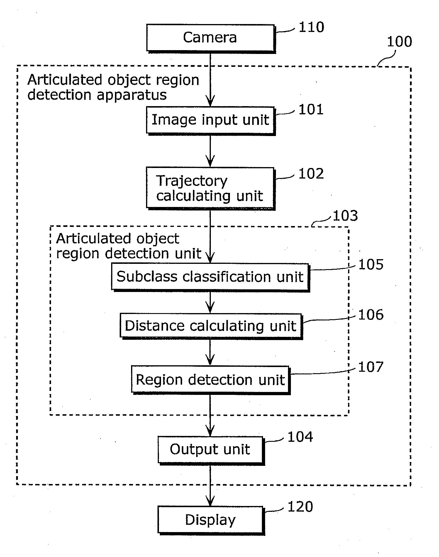
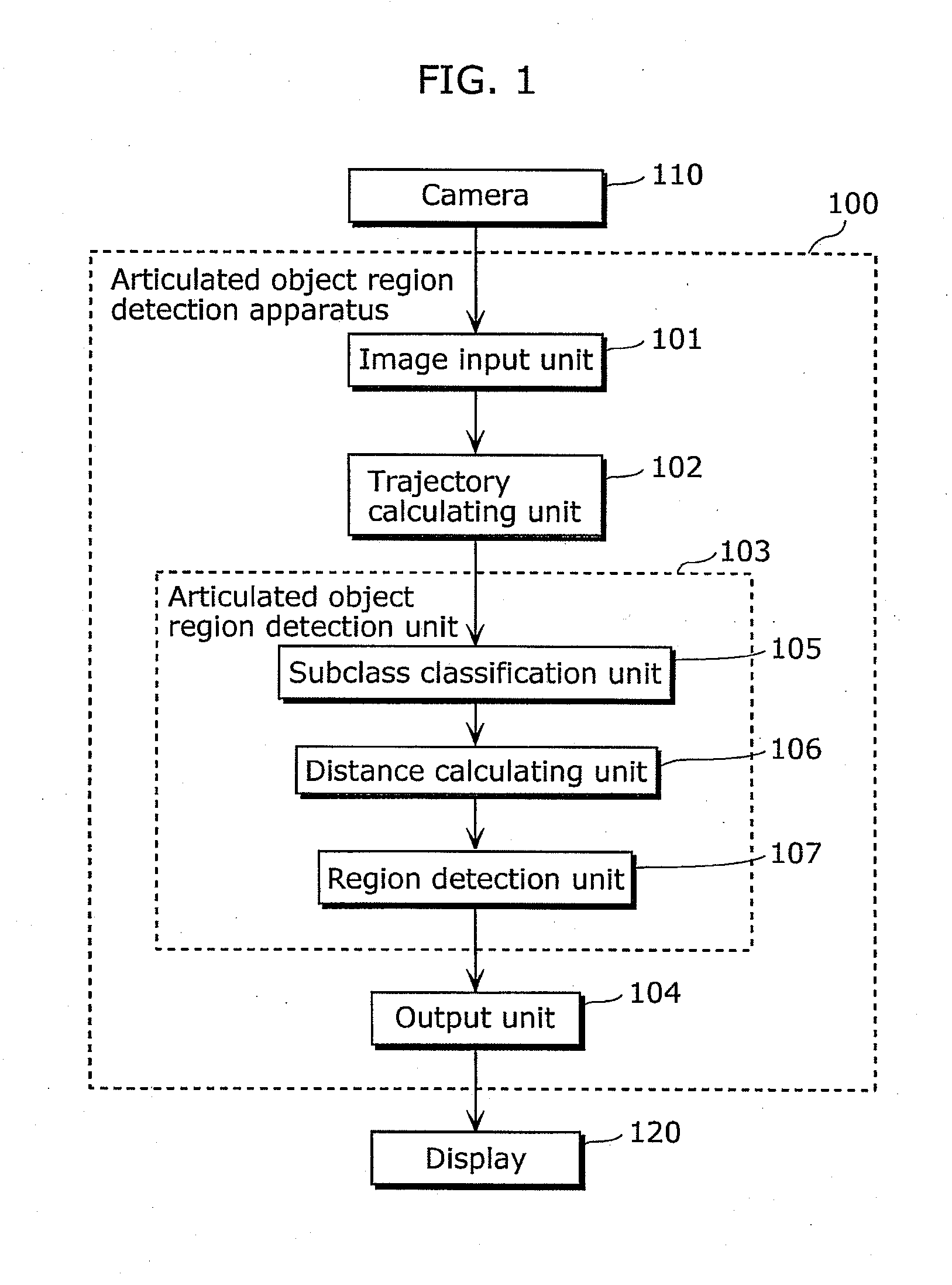
[0083]FIG. 1 is a diagram which shows a configuration of an articulated object region detection apparatus according to Embodiment 1. As shown in FIG. 1, an articulated object region detection apparatus 100 includes: an image input unit 101; a trajectory calculating unit 102; an articulated object region detection unit 103; and an output unit 104. The articulated object region detection apparatus 100 is an apparatus that detects an articulated object region in a video by performing segmentation which identifies all or part of region of the articulated object region in the video. More specifically, the articulated object region detection apparatus 100 is an apparatus that detects a region including an articulated motion, using trajectories which correspond to the respective regions included in the moving object in the video. In the present embodiment, the articulated object r...

modification 2

of Embodiment 1

[0232]The following describes an articulated object region detection apparatus according to Modification 2 of Embodiment 1 of the present invention.

[0233]In the description for the articulated object region detection apparatus in Embodiment 1, the subclass classification unit 105 obtains a subclass based on a Euclidean distance f(i, j) calculated using Expression 3. However, the operation of the subclass classification unit 105 is not limited to the above. The following describes an example of performing classification into subclasses by performing dimensionality reduction on a geodetic distance g(i, j).

[0234](a) in FIG. 21 is a diagram which shows a configuration of an articulated object region detection apparatus of Modification 2 according to Embodiment 1. As shown in (a) in FIG. 21, the articulated object region detection apparatus includes: the image input unit 101; the trajectory calculating unit 102; the articulated object region detection unit 103; and the out...

modification 3

of Embodiment 1

[0269]The following describes an articulated object region detection apparatus according to Modification 3 of Embodiment 1 of the present invention.

[0270]In the description for the articulated object region detection apparatus in Embodiment 1, the subclass classification unit 105 calculates a subclass based on a Euclidean distance f(i, j). However, the operation of the subclass classification unit 105 is not limited to the above. The following describes an example of generating a subclass, by generating geodetic distances to generate candidates for the subclass and selecting a subclass from among the candidates.

[0271](a) in FIG. 23 is a diagram which shows a configuration of an articulated object region detection apparatus of Modification 3 according to Embodiment 1. As shown in (a) in FIG. 23, the articulated object region detection apparatus includes: the image input unit 101; the trajectory calculating unit 102; the articulated object region detection unit 103; and...


PUM


Abstract

An articulated object region detection apparatus includes: a subclass classification unit which classifies trajectories into subclasses; a distance calculating unit which calculates, for each of the subclasses, a point-to-point distance and a geodetic distance between the subclass and another subclass; and a region detection unit which detects, as a region having an articulated motion, two subclasses to which trajectories corresponding to two regions connected via the same articulation and indicating the articulated motion belong, based on a temporal change in the point-to-point distance and a temporal change in the geodetic distance between two given subclasses.

Description

CROSS REFERENCE TO RELATED APPLICATION[0001]This is a continuation application of PCT application No. PCT / JP2010 / 007588 filed on Dec. 28, 2010, designating the United States of America.BACKGROUND OF THE INVENTION[0002](1) Field of the Invention[0003]The present invention relates to a technique for detecting a moving object in images based on motion information in a video including the images. The present invention relates in particular to an articulated object region detection apparatus for detecting a region of a moving object which moves changing its outline shape, such as a person, by detecting an articulated object region which is held characteristically by such a moving object.[0004](2) Description of the Related Art[0005]Research and development on a region extraction technique with which a moving object is detected by extracting a region of the moving object in an image from the image including an image of the moving object (hereinafter referred simply to as “moving object”) ...

Claims


Application Information

Patent Timeline
IPC IPC(8): G06K9/00
CPCG06T7/2033G06T2207/10016G06T2207/30196G06K9/6218G06T2207/30241G06K9/00335G06K9/6215G06T2207/30232G06T7/246G06V40/20G06V10/761G06F18/23G06F18/22
Inventor KOMOTO, AYAKOIWASAKI, MASAHIRONOBORI, KUNIO
Owner PANASONIC CORP
Learn More