Hybrid working machine having battery protecting function

Active Publication Date: 2011-10-20
KOBELCO CONSTR MASCH CO LTD
View PDF0 Cites 15 Cited by
  • Summary
  • Abstract
  • Description
  • Claims
  • Application Information

AI Technical Summary

Benefits of technology

[0006]The hybrid working machine performing the above battery charging control, however, may involve an excessive load of the battery. Specifically, in the conventional hybrid working machine, in order to swiftly recover the battery SOC to a targeted value or stabilize the battery SOC in a condition that the battery SOC is sharply lowered by discharging during a working period, performed is a control for rapid charging by full use of the battery performance determined by the detected battery temperature and SOC, in other words, performed is setting the contents of battery control based on the control at the time of discharging; this may cause an increase in the load of the battery due to continuous rapid charging in a stand-by period with no discharging, thereby damage the battery and lower the battery life.

Problems solved by technology

The hybrid working machine performing the above battery charging control, however, may involve an excessive load of the battery.
Specifically, in the conventional hybrid working machine, in order to swiftly recover the battery SOC to a targeted value or stabilize the battery SOC in a condition that the battery SOC is sharply lowered by discharging during a working period, performed is a control for rapid charging by full use of the battery performance determined by the detected battery temperature and SOC, in other words, performed is setting the contents of battery control based on the control at the time of discharging; this may cause an increase in the load of the battery due to continuous rapid charging in a stand-by period with no discharging, thereby damage the battery and lower the battery life.

Method used


Image

  • Hybrid working machine having battery protecting function
  • Hybrid working machine having battery protecting function
  • Hybrid working machine having battery protecting function

Examples


Embodiment Construction

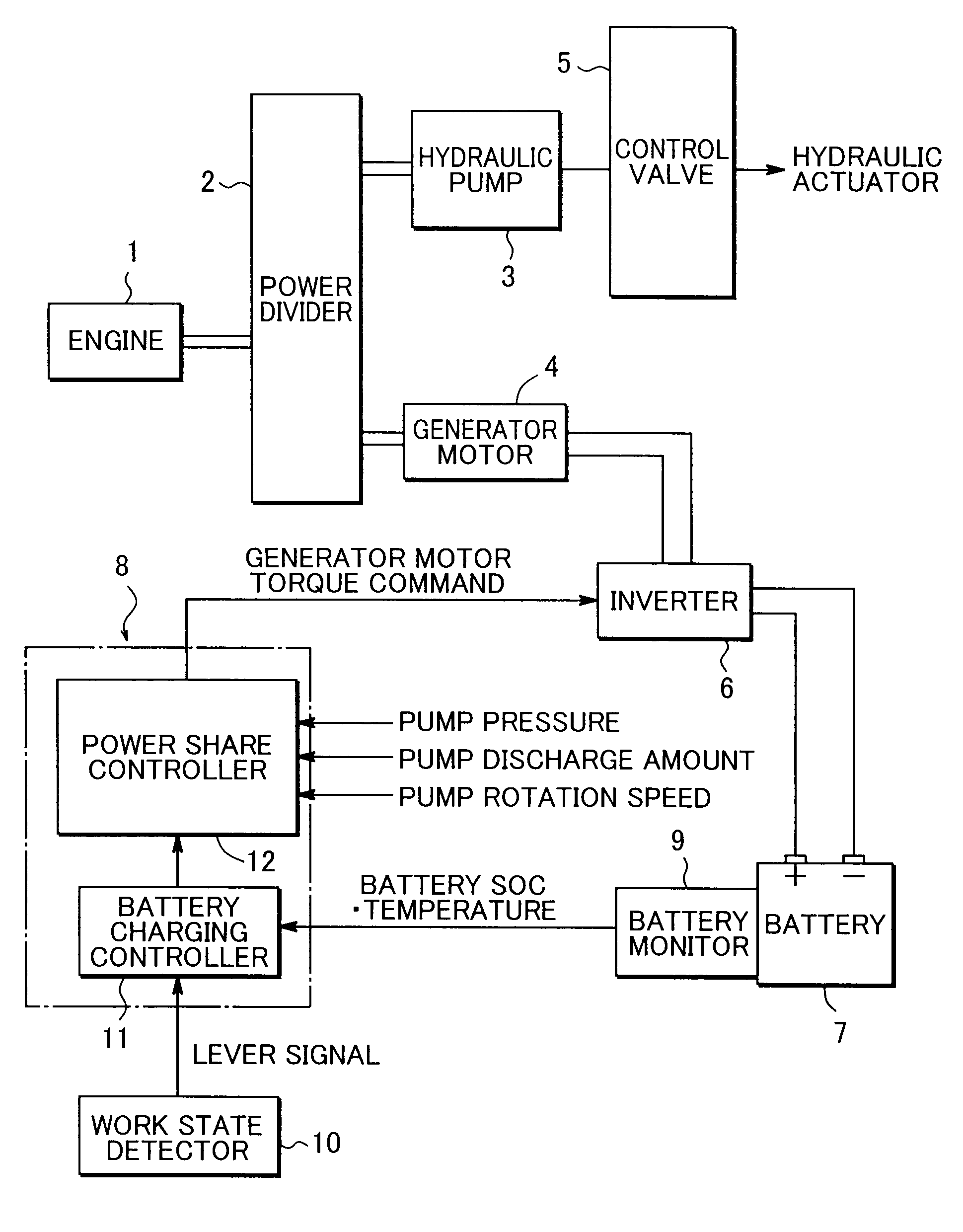
[0013]FIG. 1 shows a hybrid working machine according to an embodiment of the invention. The hybrid .working machine includes an engine 1, a power divider 2, a hydraulic pump 3, a generator motor 4, a plurality of hydraulic actuators, a plurality of control valves 5 provided for the respective actuators, a plurality of inverters 6, a battery 7, a controller 8, a battery monitor 9, and a working state detector 10.

[0014]The engine 1 is connected in parallel to the hydraulic pump 3 and to the generator motor 4 via the power divider 2 to drive the hydraulic pump 3 and the generator motor 4.

[0015]The hydraulic pump supplies hydraulic fluid to the hydraulic actuators via the respective control valves 5 to thereby drive the hydraulic actuators. In the case of a hybrid shovel, the hydraulic actuators are, for example, a boom cylinder, an arm cylinder, a bucket cylinder, a propelling hydraulic motor, ant others. FIG. 1 exemplarily shows only one control valve 5 and one hydraulic actuator. FI...


PUM


Abstract

Provided is a hybrid working machine capable of performing battery charging control both for a working period and a standby period. The hybrid working machine includes a hydraulic actuator, an engine, a hydraulic pump driven by the engine to supply hydraulic fluid to the hydraulic actuator, a battery, a generator motor connected to the engine to serve as a generator by an output power of the engine to charge the battery and serve as a motor for assisting the engine by supply of an electric power from the battery, a battery monitor detecting a battery SOC, a controller which controls a charging power of the battery depending on the battery SOC, and a working state detector detecting a working state as information for discriminating between a working period during which the hydraulic actuator is actuated and a standby period during which the hydraulic actuator is not actuated. The controller limits the charging power in the standby period in comparison with in the working period.

Description

BACKGROUND OF THE INVENTION[0001]1. Field of the Invention[0002]The present invention relates to a hybrid working machine using an engine power and a battery power in combination.[0003]2. Description of the Background Art[0004]There is known a hybrid shovel as disclosed in e.g. Japanese Unexamined Patent Publication No. 2005-237178 as a hybrid working machine. The hybrid shovel includes an engine, a hydraulic pump and a generator motor connected to the engine, a hydraulic actuator driven by hydraulic fluid ejected from the hydraulic pump, and a battery for charging an electric power generated by the generator motor. The battery supplies the electric power to the generator motor as necessary to let the generator motor perform as a motor to thereby assist the engine.[0005]The hybrid shovel is further provided with a means for detecting a battery SOC (State of Charge) indicating a charging state (charging amount) of the battery, and a means for controlling a charging power so that the ...

Claims


Application Information

Patent Timeline
IPC IPC(8): H02J7/04E02F9/20H01M10/44H01M10/48H02J7/00H02P9/04
CPCB60W30/1888Y02T10/6221Y02T10/92B60K6/48E02F9/2075B60W10/30B60W30/18054E02F9/2091B60W20/106B60W10/26B60W20/13Y02T10/62
Inventor KAGOSHIMA, MASAYUKI
Owner KOBELCO CONSTR MASCH CO LTD
Why Eureka
Try Eureka