Eureka AIR delivers breakthrough ideas for toughest innovation challenges, trusted by R&D personnel around the world.

Mobile Battery Replacement Unit

a battery replacement and mobile technology, applied in the direction of ticket-issuers, vehicle components, vehicle maintenance, etc., can solve the problems of driver stranded, no provision for providing a standalone battery replacement unit, no provision for providing a standalone portable battery replacement uni

Inactive Publication Date: 2011-10-13
GERMAN GUY +1
View PDF4 Cites 46 Cited by
  • Summary
  • Abstract
  • Description
  • Claims
  • Application Information

AI Technical Summary

Benefits of technology

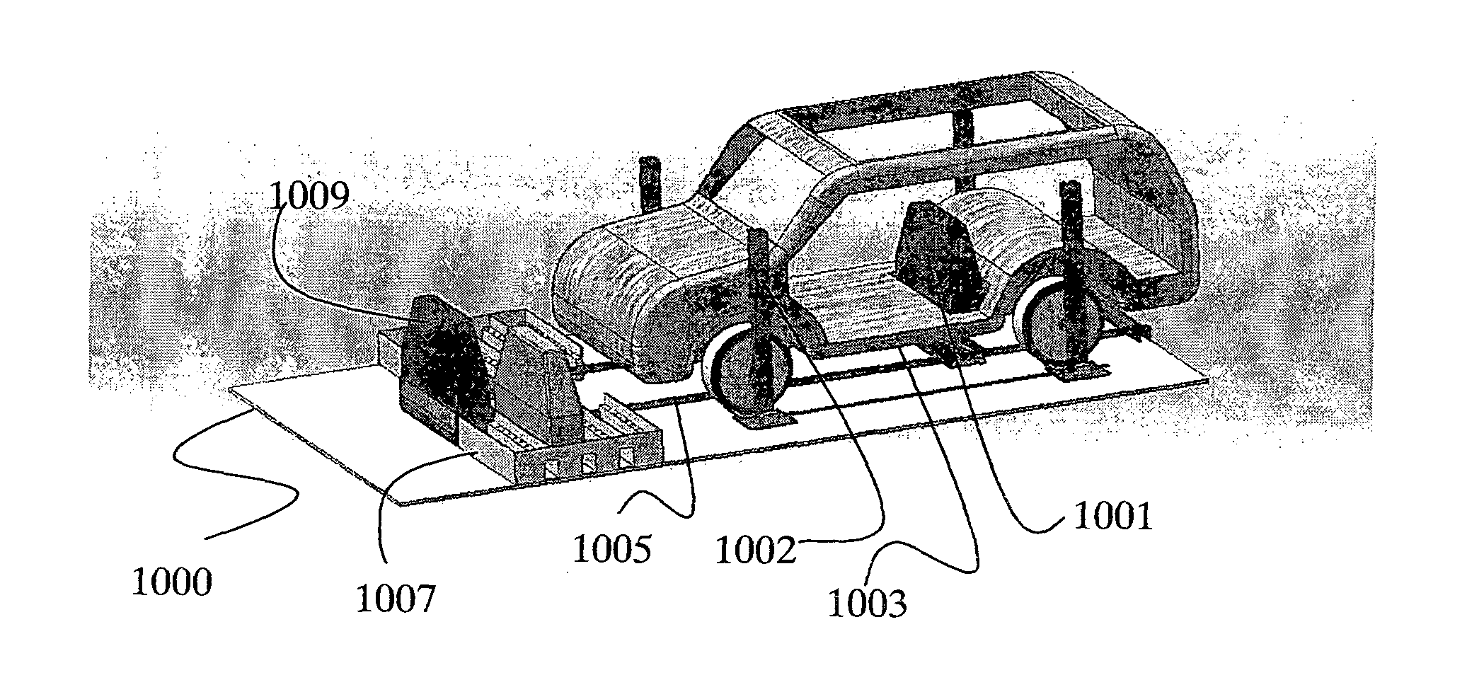
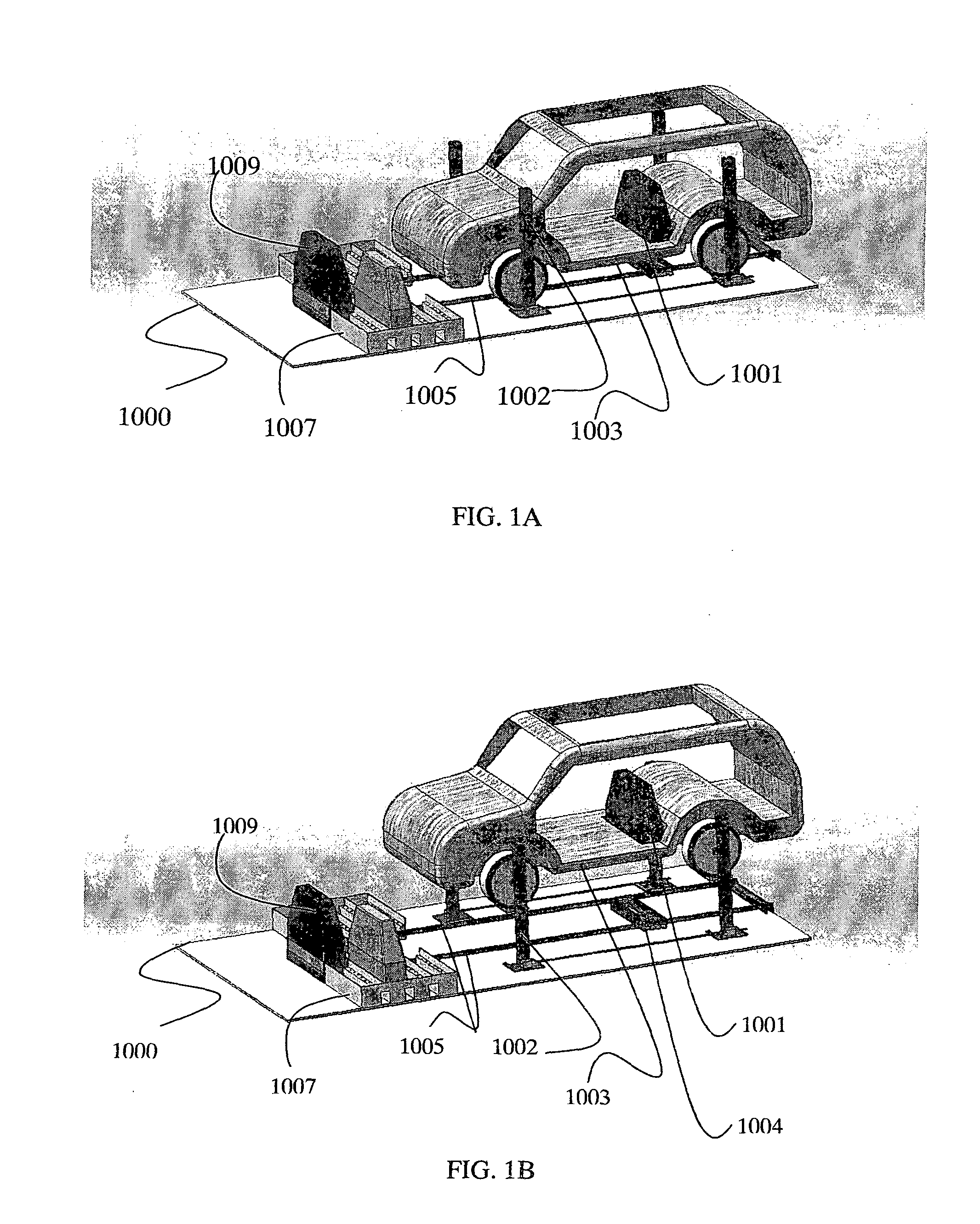
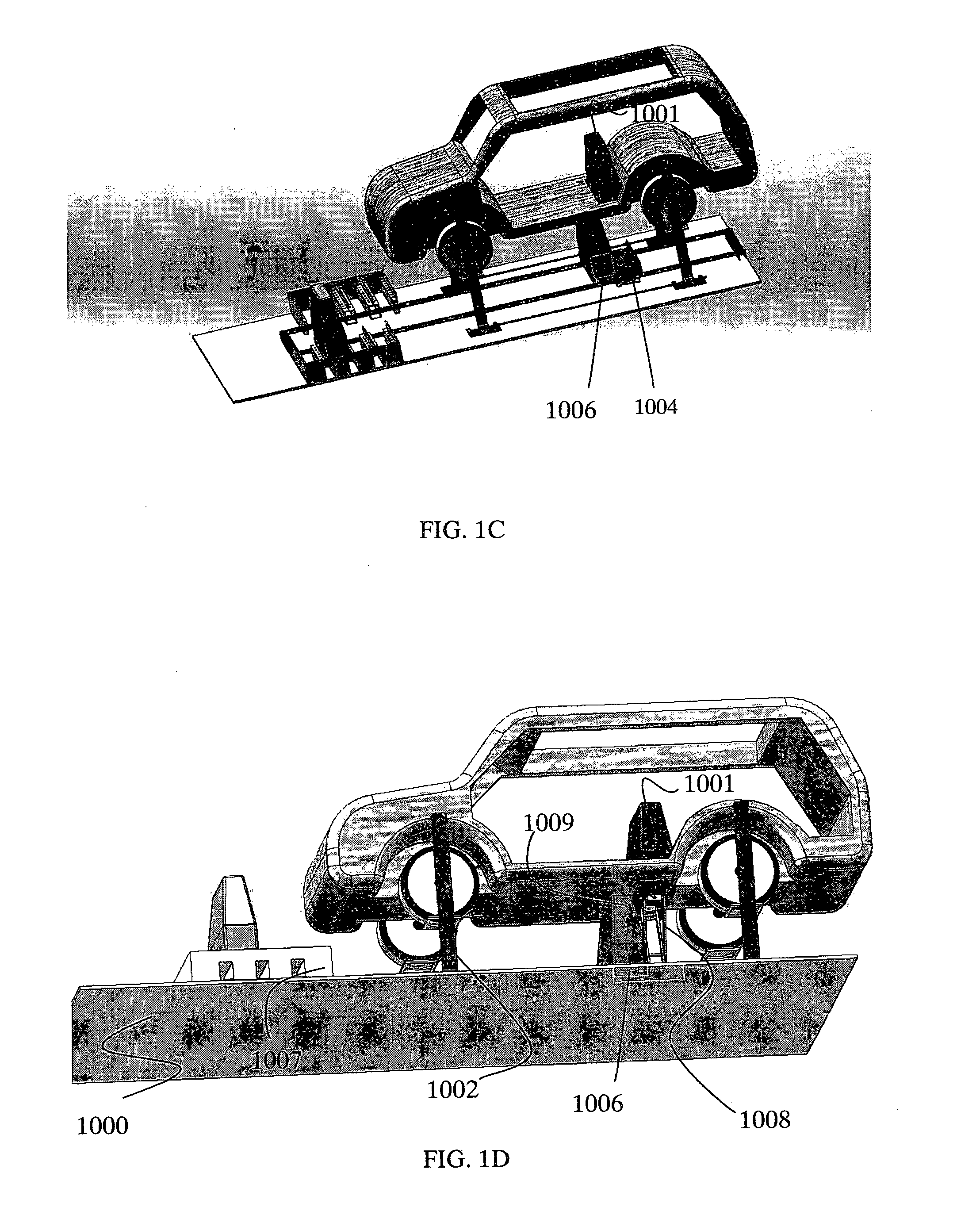
[0016]A portable device (carried on a trailer, towed e.g. by a truck, or placed at an arbitrary location) is provided that allows removal and replacement of an electric vehicle battery of ˜250 kg. The device consists of a flat platform provided with a lift and battery removal and replacement means. The trailer's ramp (or truck's ramp) allows the vehicle to drive or be towed or pushed onto the flat platform. The vehicle lift, which may be for instance a four pillar lift, raises the vehicle up to a height of ˜1 meter off the platform, allowing access to the underside of the vehicle. A receiving unit is provided that travels on rails on the platform, and is lifted by a batt

Problems solved by technology

In addition to the need for a network of battery replacement stations, there will arise the problem of drivers stranded due either to battery malfunction or simple depletion of battery energy, the BEV equivalent of being stranded without gas.
Furthermore the device relies upon a complex electromagnetic suction device for drawing the battery box into the battery tray.
Additionally there is no provision for providing a standalone battery replacement unit that can be placed in the field and used by electric vehicles to swap batteries.
Furthermore there is no provision for providing a standalone portable battery replacement unit that can be placed in the field and used by electric vehicles to swap batteries in automated fashion.
The method consists of “positioning the carriage to an electric vehicle, and easily connecting the carriage and an electric vehicle by operating a locking tool while moving the carriage at the time of replacing the battery.” However it is clear that this hand-operated wagon is not itself propelled by independent motoring means, thus limiting its use to a small area such as the environs of a car garage.
The device is clearly not capable of traveling tens of kilometers into the field to replace the battery of a stranded vehicle, nor is it capable of carrying out the replacement process in an automated fashion since its placement into proximity with the electric vehicle is manual.
It also clearly cannot be used as a standalone battery replacement unit that can be placed in the field and used by electric vehicles to swap batteries in automated fashion.

Method used


Image

  • Mobile Battery Replacement Unit
  • Mobile Battery Replacement Unit
  • Mobile Battery Replacement Unit

Examples


Embodiment Construction

[0018]The following description is provided, alongside all chapters of the present invention, so as to enable any person skilled in the art to make use of said invention and sets forth the best modes contemplated by the inventor of carrying out this invention. Various modifications, however, will remain apparent to those skilled in the art, since the generic principles of the present invention have been defined specifically to provide a mobile battery replacement unit.

[0019]In the following detailed description, numerous specific details are set forth in order to provide a thorough understanding of embodiments of the present invention. However, those skilled in the art will understand that such embodiments may be practiced without these specific details. Reference throughout this specification to “one embodiment” or “an embodiment” means that a particular feature, structure, or characteristic described in connection with the embodiment is included in at least one embodiment of the i...


PUM


Abstract

This present invention provides a method for portable electric vehicle battery replacement comprised of providing a platform adapted for holding an electric vehicle upon it, storing a plurality of electric vehicle batteries, and loading charged batteries into the electric vehicles.

Description

FIELD OF THE INVENTION[0001]The present invention relates to a method and apparatus for replacement of batteries in battery-powered electric vehicles.BACKGROUND OF THE INVENTION[0002]The present invention is in the technical field of recharge solutions for Battery Electrical Vehicles. In particular, the present invention is in the technical field of the Electrical Recharge Grid / Infrastructure for battery electrical vehicles.[0003]The widespread use of electric vehicles stands to reduce pollutant emissions and dependence upon fossil fuels. The motoring infrastructure will have to undergo some modifications before this is a practical possibility, requiring most obviously a battery replacement infrastructure, for those cases where the battery electric vehicle (BEV) driver wants to exceed the range of a single battery. Replacement instead of recharge is called for, since at the current state of the art, recharge times are far longer than most drivers are willing to wait. In addition to ...

Claims


Application Information

Patent Timeline
IPC IPC(8): B60S5/06G06Q10/00
CPCG06Q40/12B60S5/06B60L53/80Y02T10/70Y02T10/7072
Inventor GERMAN, GUYGERMAN, YOSSI
Owner GERMAN GUY
Why Eureka
Eureka Blog
Learn More