
Image pickup lens and image pickup apparatus

Active Publication Date: 2011-10-13
TIANJIN OFILM OPTO ELECTRONICS CO LTD
View PDF2 Cites 23 Cited by
  • Summary
  • Abstract
  • Description
  • Claims
  • Application Information

AI Technical Summary

Benefits of technology

[0033]The image pickup lens of the present invention is a lens system with a number of lenses being limited to a minimum of six in which the shape and power of each lens are set appropriately to satisfy Conditional Expression (1) above. This allows the image pickup lens to be structured compactly and inexpensively and to have a small F-number and high optical performance.
[0034]The image pickup apparatus of the present invention includes the image pickup lens of the present invention, so that the apparatus may be structured compactly and inexpensively. In addition, the apparatus is capable of obtaining a high resolution image and performing satisfactory imaging under low illumination conditions.

Problems solved by technology

If a plastic is used as the material of the aspherical lens, performance change due to temperature change is likely to occur, thereby causing a problem when the image pickup lens is used over a wide temperature range.
The use of a glass material for an aspherical lens, however, requires glass molding, resulting in an expensive aspherical lens.
The image pickup lens described in Patent Document 3, however, has a total length too long to be qualified as a sufficiently downsized image pickup lens.

Method used


Image

  • Image pickup lens and image pickup apparatus
  • Image pickup lens and image pickup apparatus
  • Image pickup lens and image pickup apparatus

Examples


Embodiment Construction

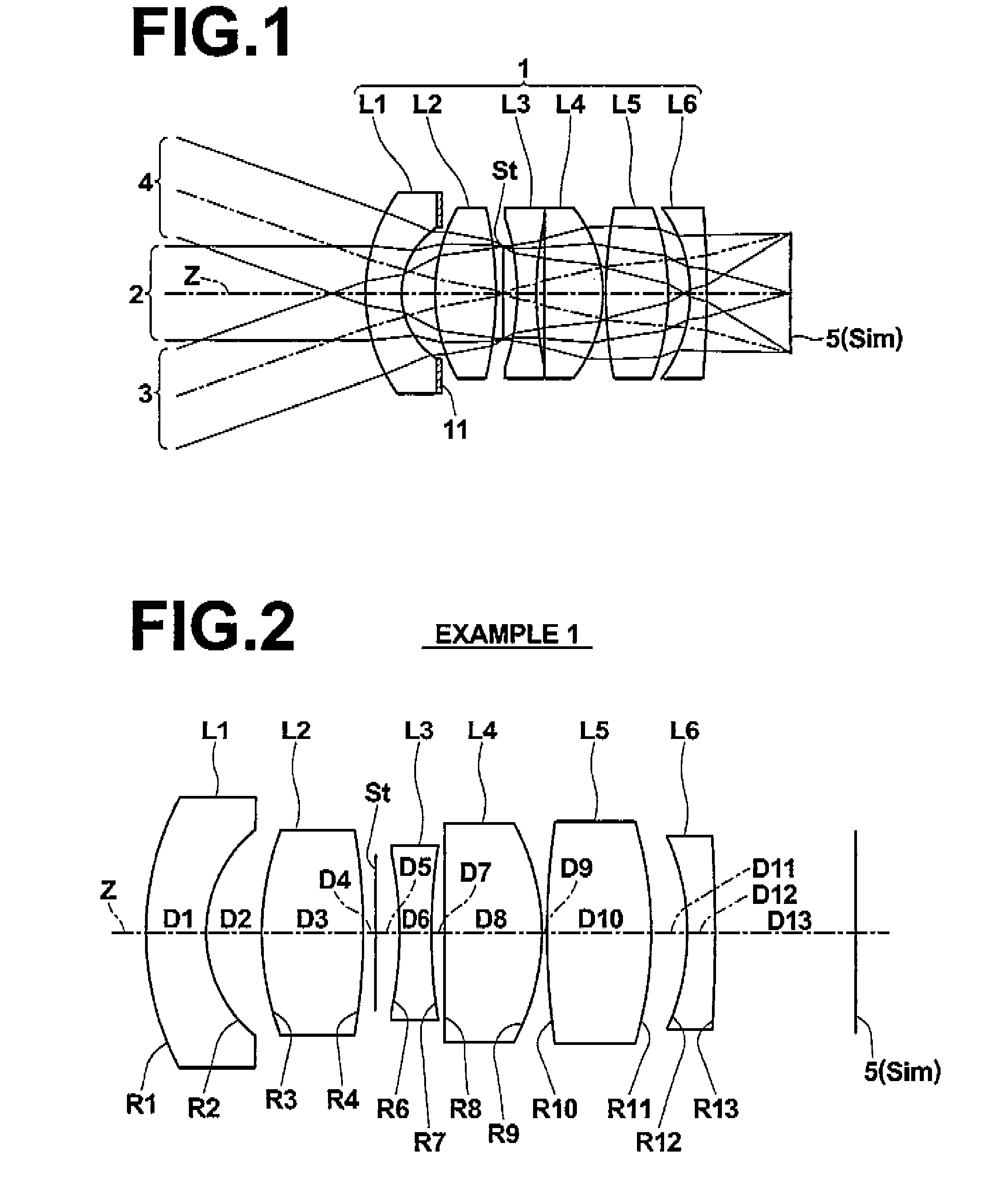
[0056]Hereinafter, embodiments of the present invention will be described with reference to the accompanying drawings. An image pickup lens according to an embodiment of the present will be described with reference to FIG. 1. FIG. 1 is a cross-sectional view of image pickup lens 1 according to an embodiment of the present invention, which corresponds to an image pickup lens of Example 1, to be described later. In FIG. 1, the right side is an object side and the left side is an image side, and on-axis light beam 2 from an object point at an infinite distance and off-axis light beams 3 and 4 at a maximum angle of view are also illustrated.

[0057]Note that FIG. 1 also shows image sensor 5 disposed on image plane Sim, considering the case in which image pickup lens 1 is applied to an image pickup apparatus. The image sensor 5 is a device that converts an optical image formed by image pickup lens 1 to an electrical signal and is constituted, for example, by a CCD image sensor, a CMOS imag...


PUM


Abstract

Disclosed is an image pickup lens having the following disposed from an object side in the order listed below: a first lens having a negative power and a meniscus shape with a concave surface on an image side; a second lens having a positive power; a third lens having a negative power; a fourth lens having a positive power; a fifth lens having a positive power; and a sixth lens having a negative power and a meniscus shape with a concave surface on the object side. The image pickup lens satisfies Conditional Expression (1) given below when a focal length of the first lens is taken as f1 and a focal length of the second lens is taken as f2. −3.0<f1 / f2<−1.6  (1)

Description

BACKGROUND OF THE INVENTION[0001]1. Field of the Invention[0002]The present invention relates to an image pickup lens and an image pickup apparatus, and more particularly to an image pickup lens appropriate for use with a vehicle camera, a surveillance camera, or the like having an image sensor, such as a CCD (charge coupled device) or a CMOS (complementary metal oxide semiconductor), and an image pickup apparatus having the image pickup lens.[0003]2. Description of the Related Art[0004]Image pickup devices, such as a vehicle camera for taking images around a vehicle, a cell phone camera, a surveillance camera installed for obtaining surveillance images or security purposes, and the like, are known. Generally, these devices include an image pickup lens and an image sensor, such as a CCD or a CMOS, for converting an image formed by the image pickup lens into an electrical signal. Downsizing and increasing of pixel count for these image sensors have been advancing year after year and,...

Claims


Application Information

Patent Timeline
IPC IPC(8): G02B9/62
CPCG02B13/0045G02B9/62
Inventor ASAMI, TARO
Owner TIANJIN OFILM OPTO ELECTRONICS CO LTD
Learn More