Pivotable Roll Bar

a roll bar and pivoting technology, applied in the field of roll bars, can solve the problems of high manufacturing cost, and achieve the effects of saving weight and cost, increasing the safety of the roll bar, and saving additional weight and cos

Active Publication Date: 2011-10-13
BOMAG
View PDF7 Cites 19 Cited by
  • Summary
  • Abstract
  • Description
  • Claims
  • Application Information

AI Technical Summary

Benefits of technology

[0009]Because the stop surfaces and the welding surfaces are implemented as edge profiles of the sheet-metal parts, parts may be saved, which would typically be welded onto the connection elements as separate parts. This not only saves weight and costs, but rather also increases the safety of the roll bar, since welding warping is reduced. Welding warping as a result of welding work on the connection elements is avoided according to the present invention in that, on the one hand, welded-on parts are extensively replaced by edge profiles and, on the other hand, the welding surfaces formed by edges are oriented essentially horizontally, onto which the parts to be welded on, namely the stand tubes, may be abutted. In this context, an edge profile is understood as a section of the sheet-metal part which is formed by simply edging the stamped-out sheet-metal tube part.
[0010]In an advantageous refinement of the invention, the pivot joints are implemented in such a way that the pivot axis runs through the pivot tubes. This saves additional weight and costs, since a separate rotation joint does not have to be provided. Instead, the rotation joint is implemented according to the present invention by a hole through the pivot tube, a hole through the connection element, and a simple screw, which is guided through the holes and terminally secured by a simple screw nut, for example.
[0011]In a further embodiment, the connection elements are materially bonded to the stand tubes using weld seams, the weld seams being at least partially peripheral fillet welds or butt welds, and being situated symmetrically with respect to the center point of the welding surfaces. Welding warping can thus be prevented as much as possible.
[0012]In a preferred embodiment of the invention, the lock has a clamping bolt and a locking screw, the clamping bolt and the locking screw being situated on the pivot tube side. In this way, comfortable locking which is free of play of the tube bow moved into the operating position is ensured, a loss of the clamping bolt and the locking screw as a result of inattentiveness being prevented.
[0013]In a further embodiment, the connection elements have recesses in the area of the clamping bolt, the recesses being implemented in such a way that the clamping bolt clamps the pivot tubes against the connection elements in the operating position and releases the pivot tubes in the transport position. This allows a simple change from the operating position (folded-up tube bow) to the transport position (folded-down tube bow) of the roll bar without additional tools, etc.
[0014]In a further advantageous refinement, the stand tubes have damping elements in the area of the connection to the frame of the construction machine. These damping means may be elastomeric, for example. The vibrations originating from the construction machine, which could result in health damage in the case of continuous load, may thus be effectively reduced.

Problems solved by technology

Since the sheet-metal parts are easily producible by stamping, high manufacturing costs as a result of machining manufacturing methods, which are required with typical connection elements, are dispensed with.

Method used


Image

  • Pivotable Roll Bar
  • Pivotable Roll Bar
  • Pivotable Roll Bar

Examples


Embodiment Construction

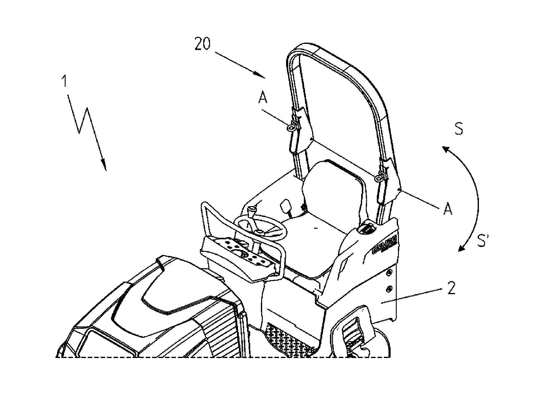
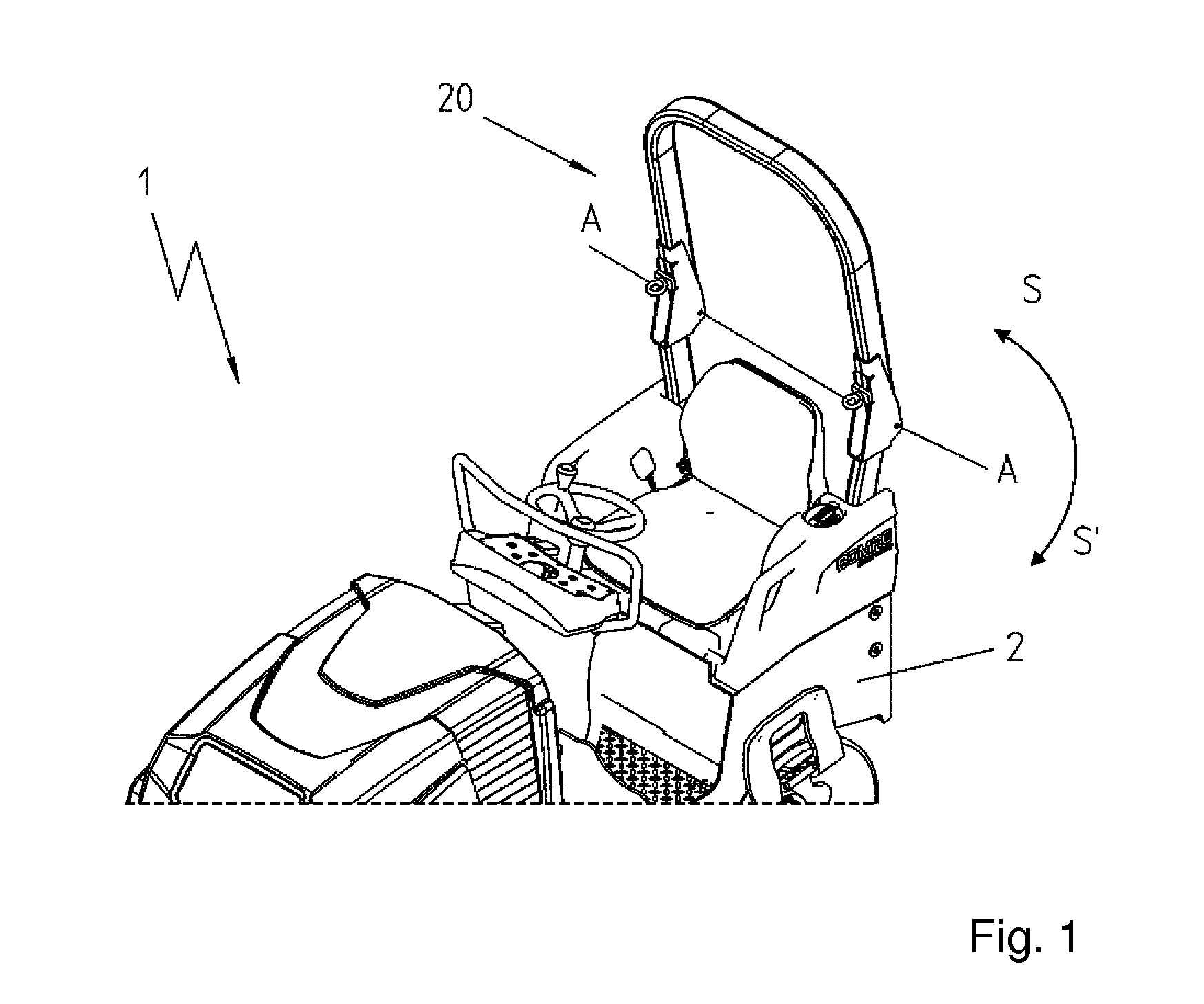
[0022]FIG. 1 shows a cab-less construction machine 1, which has a roll bar 20. The roll bar 20 is situated on the frame 2 of the construction machine 1. The upper part of the roll bar may be pivoted in the direction of the arrows S and S′ between an operating position and a transport position around the pivot axis A.

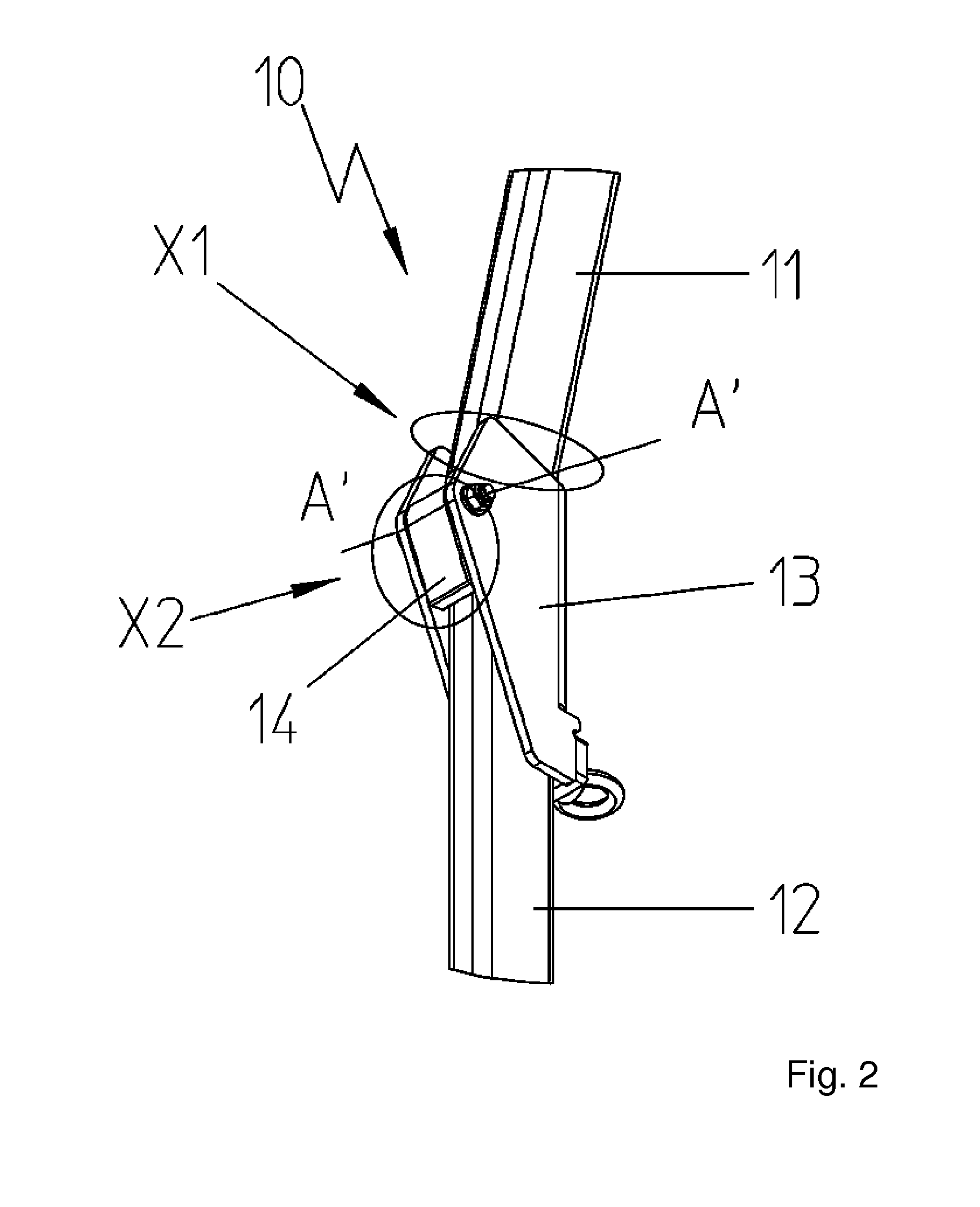
[0023]FIG. 2 shows a typical, pivotable roll bar 10 from the prior art, as from DE 10 2004 014 475 A1, for example. The solid joint reinforcement 13, which comprises a U-shaped tube section, ensures a connection of the upper spar 11 which is pivotable around the rotational axis A′ in relation to the fixed bar 12. For this purpose, the upper spar 11 is welded to the joint reinforcement 13 in the area X1. A separate component 14, which is implemented as a stop and a rotation joint, is welded to the fixed spar in the area X2. Therefore, weld warping not only occurs in the joint reinforcement 13, but rather also in the spars 11, 12.

[0024]FIGS. 3 to 6 show various views of an...


PUM


Abstract

The present invention relates to a roll bar for a cab-less construction machine, in particular a vibration roller, which is implemented so it is adjustable in height between an operating position and a transport position. The roll bar includes a pivotable tube bow, which comprises two vertical pivot tubes; two stand tubes, which are fixedly connected to the frame of the construction machine; two connection elements, via which the pivot tubes are connected to the stand tubes, the connection elements each comprising a stop surface, against which the pivot tube can be moved to, in particular pressed, in the operating position; a lock for clamping the pivot tube against the connection element in the operating position; a welding surface, to which the stand tube is materially bonded; and a pivot joint having a pivot axis, around which the pivot tubes are pivotable. The connection elements each comprise two sheet-metal parts, which are symmetrical to one another, the stop surfaces and the welding surfaces being implemented as edge profiles of the sheet-metal parts, and the welding surfaces being oriented essentially horizontally.

Description

FIELD OF THE INVENTION [0001]The invention relates to a roll bar for a cab-less construction machine, in particular a vibration roller, which is implemented so it is adjustable in height between an operating position and a transport position.BACKGROUND OF THE INVENTION [0002]The roll bar according to one embodiment of the present invention comprises a pivotable tube bow which comprises two vertical pivot tubes, two stand tubes, which are fixedly connected to the frame of the construction machine, and two connection elements, via which the pivot tubes are connected to the stand tubes. The connection elements each comprise a stop surface, against which the pivot tube can be moved to, in particular pressed, in the operating position, a lock for clamping the pivot tube against the connection element in the operating position, a welding surface, to which the stand tube is materially bonded, and a pivot joint having a pivot axis, around which the pivot tubes are pivotable.[0003]Constructi...

Claims


Application Information

Patent Timeline
Patent Type & Authority Applications(United States)
IPC IPC(8): B60R21/13
CPCB60R21/131E02F9/166E01C19/283
Inventor DUENCHEL, DIANABENDER, MATTHIASDARSCHEID, THOMAS
Owner BOMAG
Why Eureka
Try Eureka