
Wearing tool for breathing mask, and breathing mask

a breathing mask and tool technology, applied in the field of breathing masks wearing tools, can solve the problems of discomfort, pain, discomfort, etc., and achieve the effects of reducing discomfort, preventing displacement of breathing masks while used, and reducing discomfor

Active Publication Date: 2011-10-13
TEIJIN LTD
View PDF18 Cites 23 Cited by
  • Summary
  • Abstract
  • Description
  • Claims
  • Application Information

AI Technical Summary

Benefits of technology

[0015]Further, as for the breathing mask described in Patent Document 4, there is a problem of increase of costs for manufacturing the dual structured frame. For example, integral molding by a method with high difficulty such as blow molding leads to increase of costs. Even if a method is employed to mold the inner and the outer walls separately and to combine them, increase in the number of components and increase in the number of assembly processes entail.
[0032]According to the sixth aspect of the present invention, the breathing mask is provided at low cost which can prevent interference with the supply of gas for breathing.

Problems solved by technology

However, the conventional arts described above have the following types of problems.
Firstly, as for the headgear-style wearing tool described in Patent Document 1 and Patent Document 2, due to the straps pressing around the head of the user, there is the concern that a discomfort feeling such as a feeling of restraint or a feeling of pressure may occur.
Secondly, as for the cold mask-style wearing tool described in Patent Document 3, due to the elastic bands biting the bases of the ears of the user, there is the concern that a discomfort feeling or a pain may occur.
These discomfort feeling or pain may cause poor quality of sleep.
This can cause a problem with regard to the object of CPAP treatment, that is, suppressing unnecessary and harmful awakening and raising the quality of sleep.
Then the straps are twisted, and there is the concern that the breathing mask is displaced from the environs of the nostril.
This causes problems from the standpoints of therapeutic effects.
There also is the concern that the angle adjustment mechanism for adjusting the angle of the breathing mask and the wearing tool described in Patent Document 2 underlies and presses user's face when the user lies on the side, which results a discomfort feeling.
Additionally, if an attempt is made to adjust the angle of the breathing mask relative to the height of the nasal bridge or the direction of the nostrils of the user while the breathing mask is worn, gaps are likely to occur at the environs of the nostrils, and thus there is the concern that it becomes necessary to wear the wearing tool again after the angle adjustment.
This causes problems from the standpoints of user convenience.
Further, as for the breathing mask described in Patent Document 4, there is a problem of increase of costs for manufacturing the dual structured frame.
For example, integral molding by a method with high difficulty such as blow molding leads to increase of costs.

Method used


Image

  • Wearing tool for breathing mask, and breathing mask
  • Wearing tool for breathing mask, and breathing mask
  • Wearing tool for breathing mask, and breathing mask

Examples


third embodiment

[3] Third Embodiment of Wearing Tool

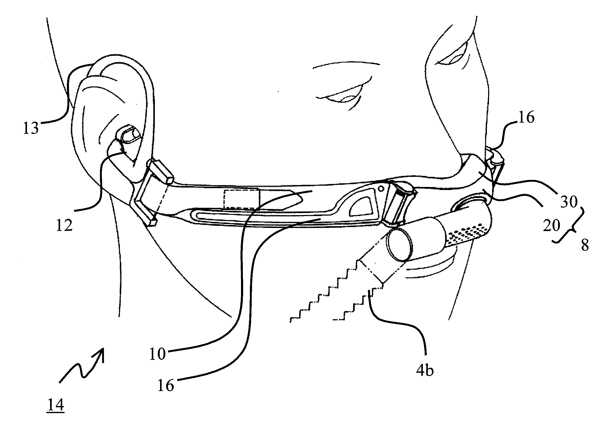
[0143]In the third embodiment, the wearing tool 14 has supporting member provided along the longitudinal direction of the wearing tool 14.

[0144]FIG. 17 is a drawing for explaining configuration of the supporting member. FIG. 17A shows, by using the right-side strap 10 of the first embodiment as an example, the supporting member provided on the strap 10. However, the third embodiment can be practiced solely, or together with any of the wearing tools of the first, the second, or another embodiments. And the breathing mask in practicing the third embodiment can be a breathing mask which covers only the environs of nostrils, or a breathing mask which covers the nostrils and the mouth of the user.

[0145]As shown in FIG. 17A, the strap 10 is provided with, as the supporting member, a panel 16 which extends in the longitudinal direction of the strap 10 and has a certain length in the width direction, and has greater rigidity than the strap 10. The panel 1...

fourth embodiment

[4] Fourth Embodiment of the Wearing Tool

[0156]In the fourth embodiment, the wearing tool 14 has the supporting member provided in the longitudinal direction. This supporting member comprises a first plate-shape member which is fixed to the breathing mask 8 and a second plate-shape member which is fixed to said connecting member. And, the first and the second plate-shape members are configured to be rotatable. The fourth embodiment can be solely practiced, or can be practice with any of wearing tools of the first and the second embodiments, and another the wearing tool. The breathing mask in the practice of the fourth embodiment can be a breathing mask which covers only the environs of the nostrils of the user, or a breathing mask which covers the nostrils and the mouth of the user.

[0157]FIG. 19 is a drawing for explaining the panel 16 as the supporting member. FIG. 19A shows a plane view of the right-side panel 16, and FIG. 19B shows a cross-sectional view on an arrow P′. The panel...

first embodiment

[5] First Embodiment of Breathing Mask

[0174]First, FIG. 23 is used to explain the overall configuration of the breathing mask 8. The breathing mask 8 has a frame 20 which forms the contour and is also connected to the flexible hose 4b, and a cushion 30 which is used in combination with the frame 20 and is in contact with the environs of the nostrils of the user to cover it.

[0175]Here the configuration of a breathing mask of the prior art is explained, and then this embodiment is explained.

[0176]FIG. 24 is a drawing for explaining the configuration of a breathing mask of the prior art. In FIG. 24, a cross-sectional view of the breathing mask is shown schematically. The bottom of the figure corresponds to the position of the environs of the nostrils of the user lying on the back. In general, a breathing mask has a frame 200 which forms the outer shell of the breathing mask, and a cushion 300 provided on the periphery of the opening portion 204 of the frame 200 and which abuts the envi...


PUM


Abstract

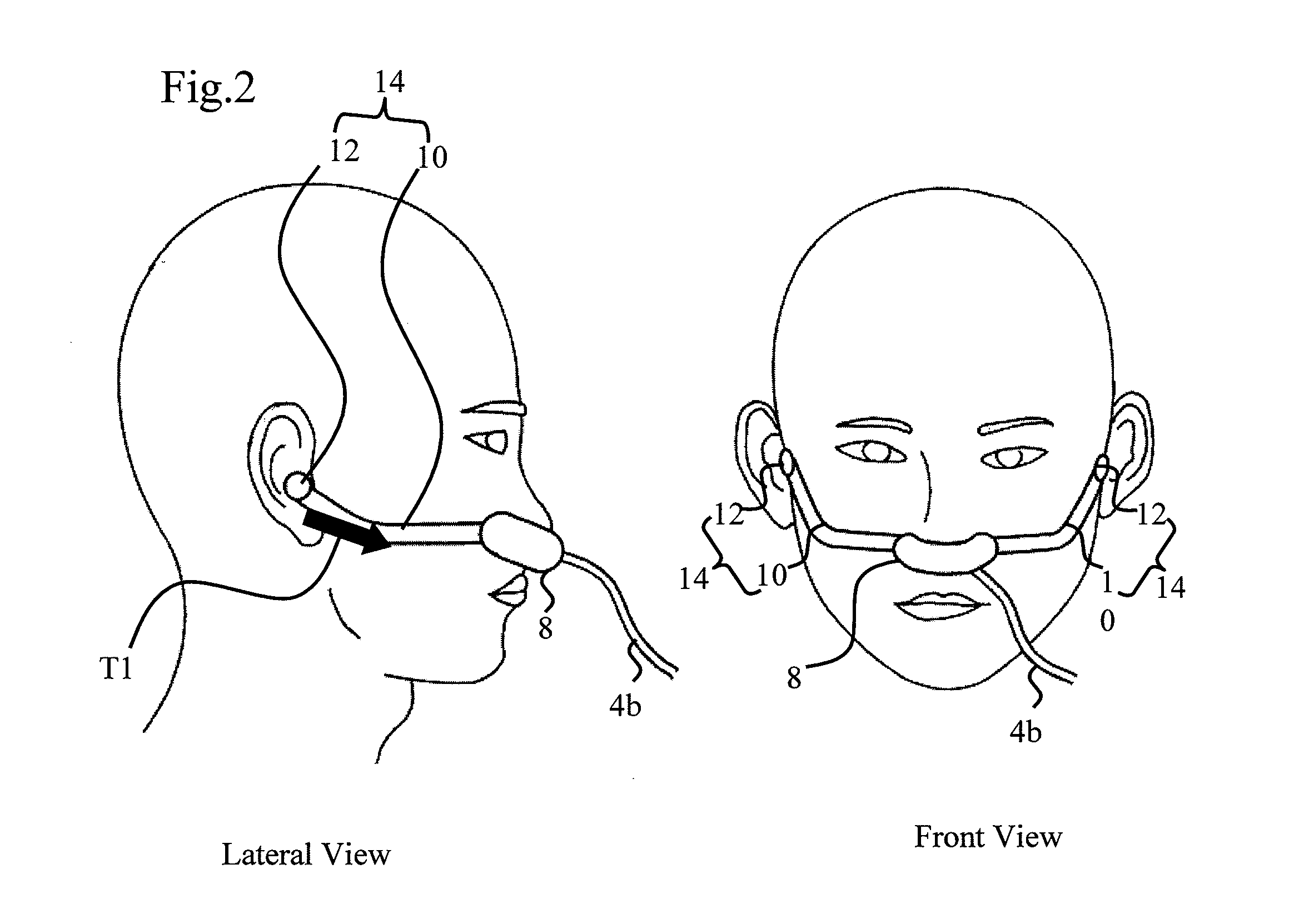
For reducing a discomfort feeling brought by wearing a breathing mask, a wearing tool for the breathing mask which covers nostrils of a user and supplies gas for breathing to the nostrils comprises a pair of connecting members each of which has a longitudinal shape and has a first end portion which is connected to the breathing mask, and a pair of fixing members each of which is connected to a second end portion of the fixing member and is plugged in the tragus of the user. Hence a discomfort feeling due to restraining around the head of the user can be reduced.

Description

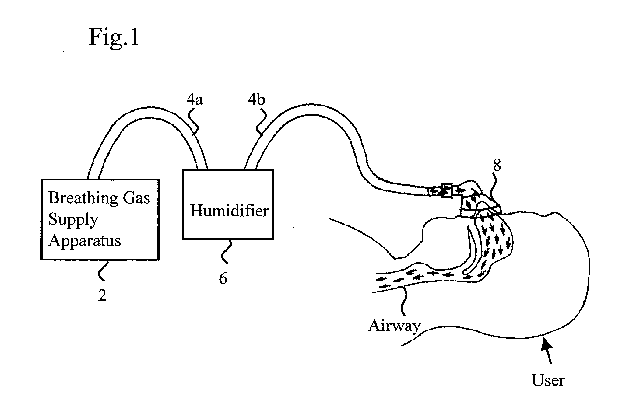
FIELD OF THE INVENTION[0001]The present invention relates to a breathing mask which covers a user's nostrils and supplies pressurized gas for breathing to the nostrils, and to a wearing tool for the breathing mask.BACKGROUND OF THE INVENTION[0002]As a treatment method for sleep apnea syndrome, such that an airway is obstructed and becomes apnea during sleep, CPAP (Continuous Positive Airway Pressure) treatment is known, in which gas for breathing pressurized in the range from 392 to 1961 Pa is continuously supplied to the nostrils of a patient when sleeping, so that the airway of the patient is expanded, and thus the patient breathing is assisted.[0003]For CPAP treatment, a breathing gas supply apparatus is used, which has a function for generating gas for breathing by pressurizing the air. Gas for breathing generated by the breathing gas supply apparatus is supplied through a flexible hose to a breathing mask. The breathing mask, as an example is described in Patent Document 1, is ...

Claims


Application Information

Patent Timeline
IPC IPC(8): A61M16/04
CPCA61M16/06A61M16/0666A61M16/0683A61M16/0622A61M2210/0618A61M2210/0662A61M2209/088A61M2205/3633A61M16/0808A61M16/16
Inventor OMURA, KEIKOFUJIMOTO, SHINYANISHIJIMA, AKITO
Owner TEIJIN LTD
Learn More