Gear measurement method

a technology of gear and measurement method, applied in the direction of measuring circumference, measuring devices, instruments, etc., to achieve the effect of reducing the size of the machine, reducing the travel of the probe, and reducing the moving range of the probe in the measuremen

Inactive Publication Date: 2011-10-13
MITSUBISHI HEAVY IND LTD
View PDF0 Cites 7 Cited by
  • Summary
  • Abstract
  • Description
  • Claims
  • Application Information

AI Technical Summary

Benefits of technology

[0009]Accordingly, in the gear measurement method according to the present invention, since the amount of travel of a probe can be reduced, the moving range of the probe in a measurement becomes small. Thus, the size of a machine can be reduced.

Problems solved by technology

Moreover, in the case where a gear to be machined is large, since a defective must not be produced, finishing is performed after machining and measurement are repeated several times with a machining allowance left.
However, separately providing a gear cutting machine and a gear measuring machine produces the necessity of the work of replacing a gear to be machined therebetween.

Method used


Image

  • Gear measurement method
  • Gear measurement method
  • Gear measurement method

Examples


embodiment

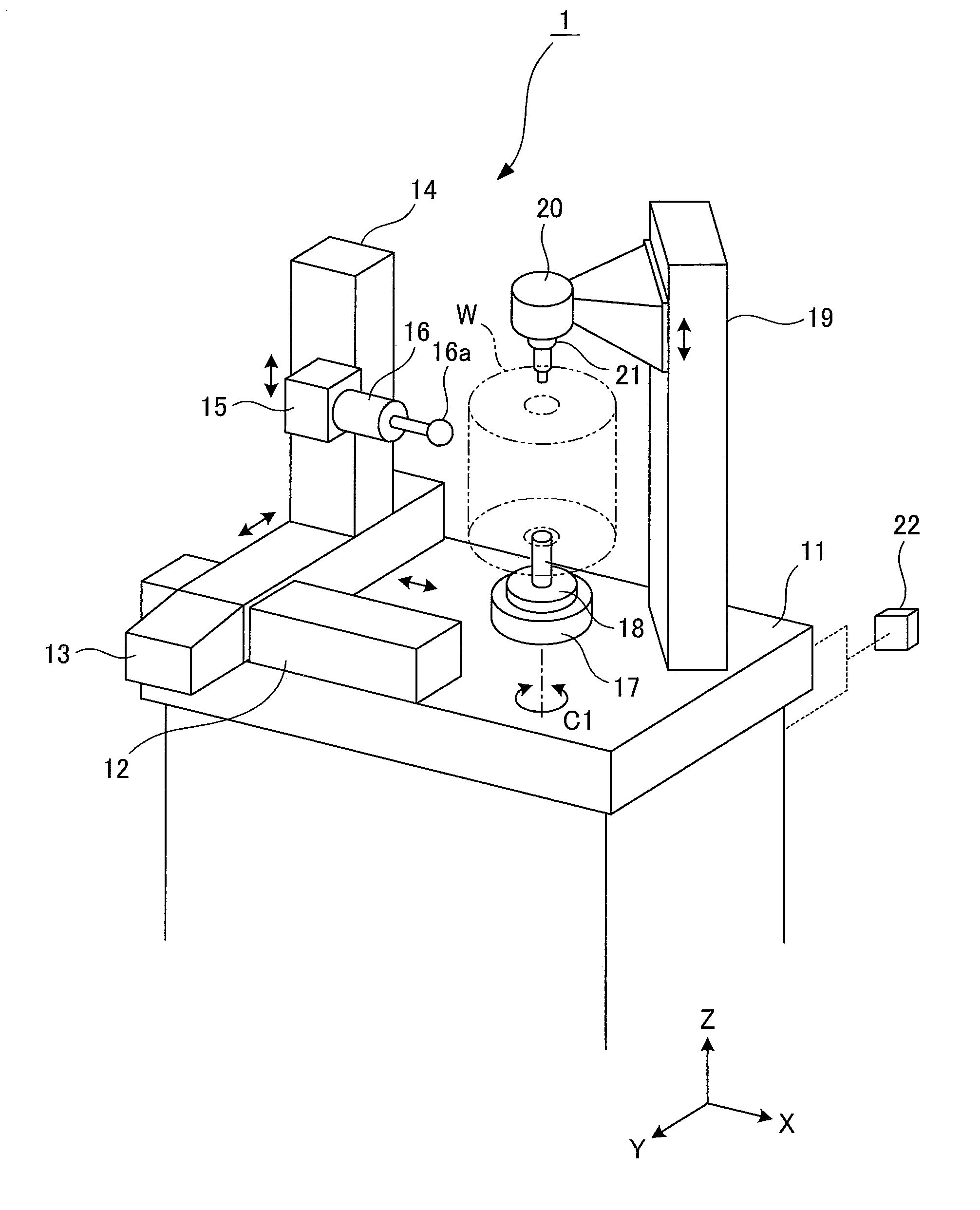
[0015]A gear measuring instrument 1 shown in FIG. 1 is intended to measure the tooth profile of a large workpiece (gear to be measured, gear to be machined) W after grinding such as shown in FIG. 2.

[0016]As shown in FIG. 1, abase 11 is provided in a lower portion of the gear measuring instrument 1. On the upper surface of this base 11, a guide rail 12 is fixed to extend in the direction of a horizontal X axis, and a guide rail 13 is slidably supported to extend in the direction of a horizontal Y axis. The guide rails 12 and 13 are disposed perpendicular to each other. The guide rail 13 is supported to be movable in the direction of the X axis with respect to the guide rail 12. Further, on the guide rail 13, a guide rail 14 extending in the direction of a vertical Z axis is supported to be movable in the direction of the Y axis.

[0017]On a side surface of the guide rail 14, a movable body 15 is supported to be movable up and down in the direction of the Z axis. A measuring device 16 i...


PUM


Abstract

An object of the present invention is to provide a gear measurement method which makes it possible to reduce the size of a machine by reducing the amount of travel of a probe and thus reducing a moving range of the probe in a measurement. To achieve the object, a gear measurement method for measuring the tooth profile of a workpiece (W) by linearly moving a probe (16a) in accordance with the rotation of the workpiece (W), with the probe (16a) in contact with a right tooth face (WR) or a left tooth face (WL) of the workpiece (W), by synchronous control of the movement of the probe (16a) and the rotation of the workpiece (W), includes setting a tangent line (L) touching the tangent point (A) rotated from a tangent point (Ao) on the base circle (Wb) of the workpiece (W) in one direction by a predetermined rotation angle (α) and a tangent line (L′) touching the tangent point (A′) positioned by being rotated from the tangent point (Ao) on the base circle (Wb) of the workpiece (W) in the other direction by the predetermined rotation angle (α), moving the probe (16a) along the tangent line (L) when measuring the right tooth face (WR), moving the probe (16a) along the tangent line (L′) when measuring the left tooth face (WL), and setting the respective midpoints of the segments connecting the measurement start points (B, B′) to the measurement end points (C, C′) at the intersection point (M) of the tangent lines (L, L′).

Description

TECHNICAL FIELD[0001]The present invention relates to a gear measurement method for measuring a tooth profile of a gear to be measured.BACKGROUND ART[0002]In general, when a gear to be machined is machined by a gear cutting machine such as a gear shaping machine, a gear hobbing machine, and a gear grinding machine, after the shape of the tooth surface, including the tooth profile and the tooth trace, of at least one machined gear taken from a machined lot is measured, the accuracy thereof is checked, and then the remaining unmachined lot is machined. Moreover, in the case where a gear to be machined is large, since a defective must not be produced, finishing is performed after machining and measurement are repeated several times with a machining allowance left. Such measurement of the shape of the tooth surface of a gear to be machined has been performed with a gear measuring machine independent of a gear cutting machine.[0003]However, separately providing a gear cutting machine and...

Claims


Application Information

Patent Timeline
Patent Type & Authority Applications(United States)
IPC IPC(8): G01D21/00
CPCG01B5/202G01B3/18G01B5/025
Inventor OTSUKI, NAOHIROYANASE, YOSHIKOTOMASUO, KOICHI
Owner MITSUBISHI HEAVY IND LTD
Why Eureka
Try Eureka