
Bending-insertion assisting instrument and insertion path securing apparatus

a technology of assisting instruments and insertion paths, which is applied in the field of bending-insertion assisting instruments and insertion path securing apparatus, can solve the problems of difficult to retain the shape of each bending position and the inability to retain the bent shape, so as to achieve the effect of reliable securement of the insertion path

Inactive Publication Date: 2011-10-06
FUJIFILM CORP
View PDF3 Cites 8 Cited by
  • Summary
  • Abstract
  • Description
  • Claims
  • Application Information

AI Technical Summary

Benefits of technology

[0008]An object of the invention is to provide a bending-insertion assisting instrument that can make various pieces of medical equipment reliably follow the bent shape of an insertion path and always accurately maintain the insertion path of the various pieces of medical equipment in a desired shape even though the insertion path along which the various pieces of medical equipment are inserted into the body cavity has a complicated shape, and an insertion path securing apparatus using the bending-insertion assisting instrument. Further, another object of the invention is to reduce the diameter of an insertion path securing apparatus.
[0013]According to the bending-insertion assisting instrument and the insertion path securing apparatus of the invention, it may be possible to reliably secure an insertion path having a desired shape while reliably retaining the shape of the sheath tube having been bent once.

Problems solved by technology

However, if an insertion path to be set has a complicatedly bent shape, it is difficult to continue to retain the shape of each bending position of the insertion path as it is.
However, at a portion of the sheath tube that is closer to the base end than the foremost portion and which has already been bent, it is not possible to retain the bent shape, which has been formed once, as it is.

Method used


Image

  • Bending-insertion assisting instrument and insertion path securing apparatus
  • Bending-insertion assisting instrument and insertion path securing apparatus
  • Bending-insertion assisting instrument and insertion path securing apparatus

Examples


Embodiment Construction

[0033]An embodiment of the invention will be described in detail below with reference to the drawings.

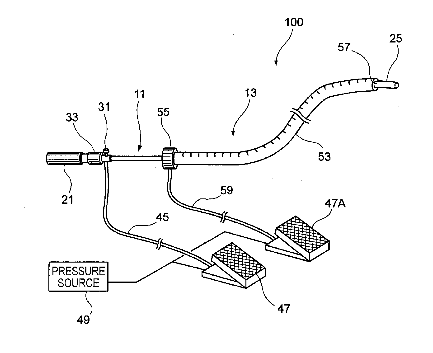
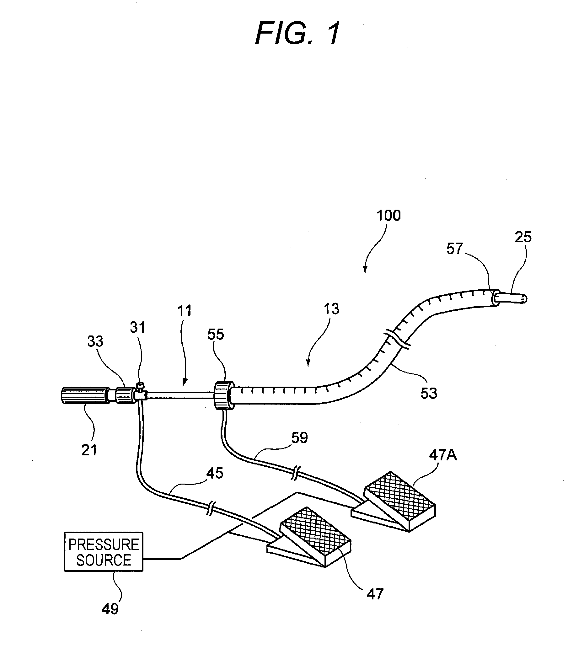
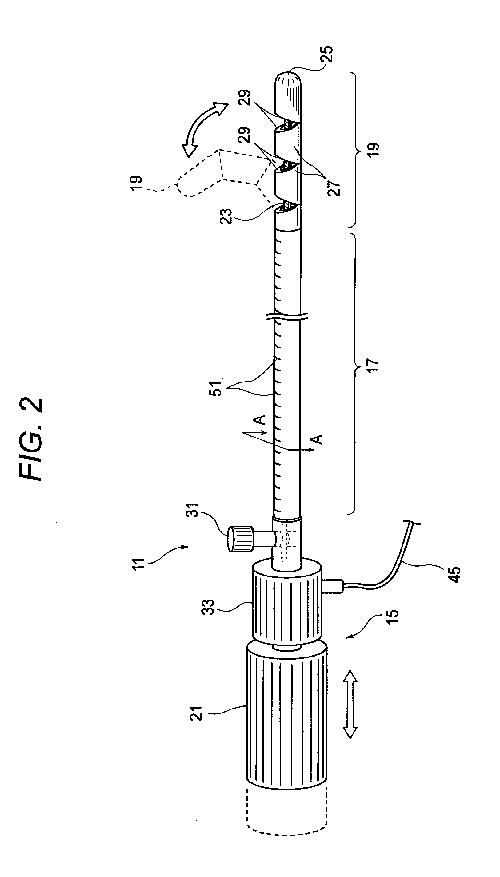
[0034]FIG. 1 is a view illustrating an embodiment of the invention, and is a view showing the entire configuration of an insertion path securing apparatus. FIG. 2 is a view showing the appearance of a bending-insertion assisting instrument. FIG. 3 is a sectional view schematically showing a cross-section taken along a line A-A of FIG. 2.

[0035]As shown in FIG. 1, an insertion path securing apparatus 100 is to secure a bent insertion path in a desired shape when medical instruments (various medical instruments such as an endoscope and a treatment instrument) are inserted into the body cavity. The insertion path securing apparatus 100 includes a bending-insertion assisting instrument 11 and a long tube-like sheath tube 13.

[0036]Referring to FIGS. 2 and 3, the bending-insertion assisting instrument 11 includes a bending operation portion 15, a long intermediate extension portion 17, a t...


PUM


Abstract

An insertion path securing apparatus includes a bending-insertion assisting instrument and a sheath tube that includes a first lumen where the bending-insertion assisting instrument is inserted. The bending-insertion assisting instrument includes a bendable tip bending portion, an intermediate extension portion being connected to the tip bending portion, and a bending operation portion being disposed at a base end of the intermediate extension portion. The state of the intermediate extension portion can be selectively switched to a variable-shape state where the bent shape of the intermediate extension portion can be freely changed and a shape retaining state where the bent shape of the intermediate extension portion is retained. The sheath tube includes a tube-like insertion portion of which the state can be selectively switched to a variable-shape state and a shape retaining state, and an operation portion that is disposed at a base end of the tube-like insertion portion.

Description

CROSS-REFERENCE TO RELATED APPLICATIONS[0001]This application claims the benefit of Japanese Patent Application No. 2010-084417, filed on Mar. 31, 2010, the entire contents of which are hereby incorporated by reference, the same as if set forth at length; the entire of which are incorporated herein by reference.BACKGROUND OF THE INVENTION[0002]1. Technical Field[0003]The present invention relates to a bending-insertion assisting instrument and an insertion path securing apparatus using the bending-insertion assisting instrument.[0004]2. Description of Related Art[0005]When a treatment or an observation is to be made in a body cavity with various medical instruments such as an endoscope, a tube-like sheath tube (overtube) having flexibility is inserted into the body cavity and various medical instruments are inserted into the sheath tube, so that an insertion path into the body cavity is secured. Further, a sheath tube is also used to form a small hole by the incision of the wall of ...

Claims


Application Information

Patent Timeline
IPC IPC(8): A61B1/00
CPCA61B1/00131A61B1/303A61B1/0055A61B1/0051
Inventor IWASAKA, MASAYUKI
Owner FUJIFILM CORP
Learn More