Projector

a projector and projector technology, applied in the field of projectors, can solve the problems of reducing the flow speed of the projector, unable to supply the cooling target in a preferable condition with sufficient flow of cooling air, and unable to achieve the effect of cooling the cooling target in a preferable condition, so as to achieve the effect of improving the efficiency of cooling the cooling targ

Active Publication Date: 2011-10-06
SEIKO EPSON CORP
View PDF7 Cites 5 Cited by
  • Summary
  • Abstract
  • Description
  • Claims
  • Application Information

AI Technical Summary

Benefits of technology

An advantage of some aspects of the invention is to provide a projector capable of improving the efficiency of cooling a cooling target.
According to this structure, the respective ducts introduce the cooling airs discharged from the cooling fans toward the cooling target in directions different from each other. In addition, the plural ducts communicate with each other at the other end and have the outlet port through which the cooling air flows out. In this arrangement, the respective cooling airs discharged from the plural cooling fans are guided from the one end to the other end of each of the ducts, and collide with each other at the other end at the position of the outlet port. Then, the cooling airs after collision with each other flow out from the outlet port toward the cooling target. According to the structure in this aspect of the invention which changes the channel directions of the cooling airs discharged from the cooling fans by collision between each other, the pressure losses of the cooling airs become lower than the pressure loss of a structure which changes the channel direction by collision with the wall surface or the like of the duct in the related art described above. Thus, the flow speeds of the cooling airs do not drop. More specifically, the cooling airs can be guided from the outlet port toward the cooling target while maintaining the same flow speeds even after the collision. In this case, the flow amounts of the cooling airs introduced toward the cooling target do not decrease, which allows sufficient flow amounts of the cooling airs to be supplied to the cooling target. Accordingly, the efficiency of cooling the cooling target improves.
According to this aspect of the invention, however, the respective ducts are so constructed as to communicate with each other in a linear shape at the position of the outlet port. In this case, the cooling airs discharged from the respective cooling fans collide with each other at the position of the outlet port in directions opposed to each other. In this case, a part of the cooling airs does not flow to the position of the wall surface of the duct. Thus, the cooling airs after the collision can flow toward the cooling target from the outlet port without lowering the flow speeds, which further improves the efficiency of cooling the cooling target.
According to this structure, the cross-sectional area of the duct decreases in the direction toward the outlet port. Thus, the flow speeds of the cooling airs discharged from the plural cooling fans increase in the direction toward the outlet port. In this case, the flow amounts of the cooling airs supplied to the cooling target can be raised in accordance with the increase in the flow speeds of the cooling airs at the position of the outlet port. Accordingly, the efficiency of cooling the cooling target further improves.

Problems solved by technology

According to the technology disclosed in JP-A-2005-338236, however, the cooling air colliding with the wall surface of the duct at the other end generates friction on the wall surface, and lowers its flow speed due to pressure loss thus produced.
Under this condition, a sufficient flow amount of cooling air for cooling the cooling target in a preferable condition is difficult to be supplied to the cooling target.

Method used


Image

  • Projector
  • Projector
  • Projector

Examples


embodiment

Modification of Embodiment

The invention is not limited to the embodiment described herein but may be practiced otherwise without departing from the scope of the invention. Therefore, modifications, improvements and the like including the following changes may be made.

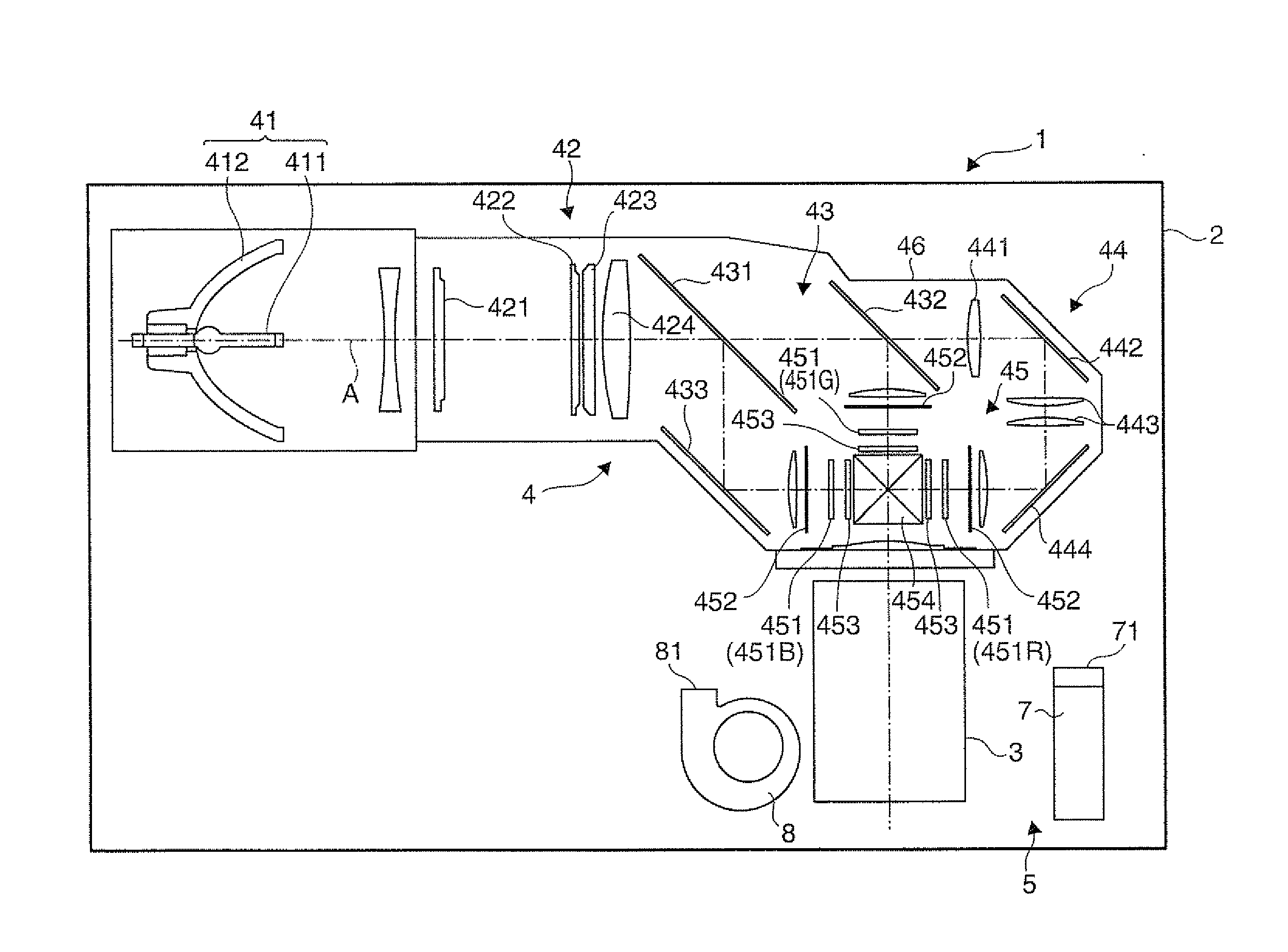
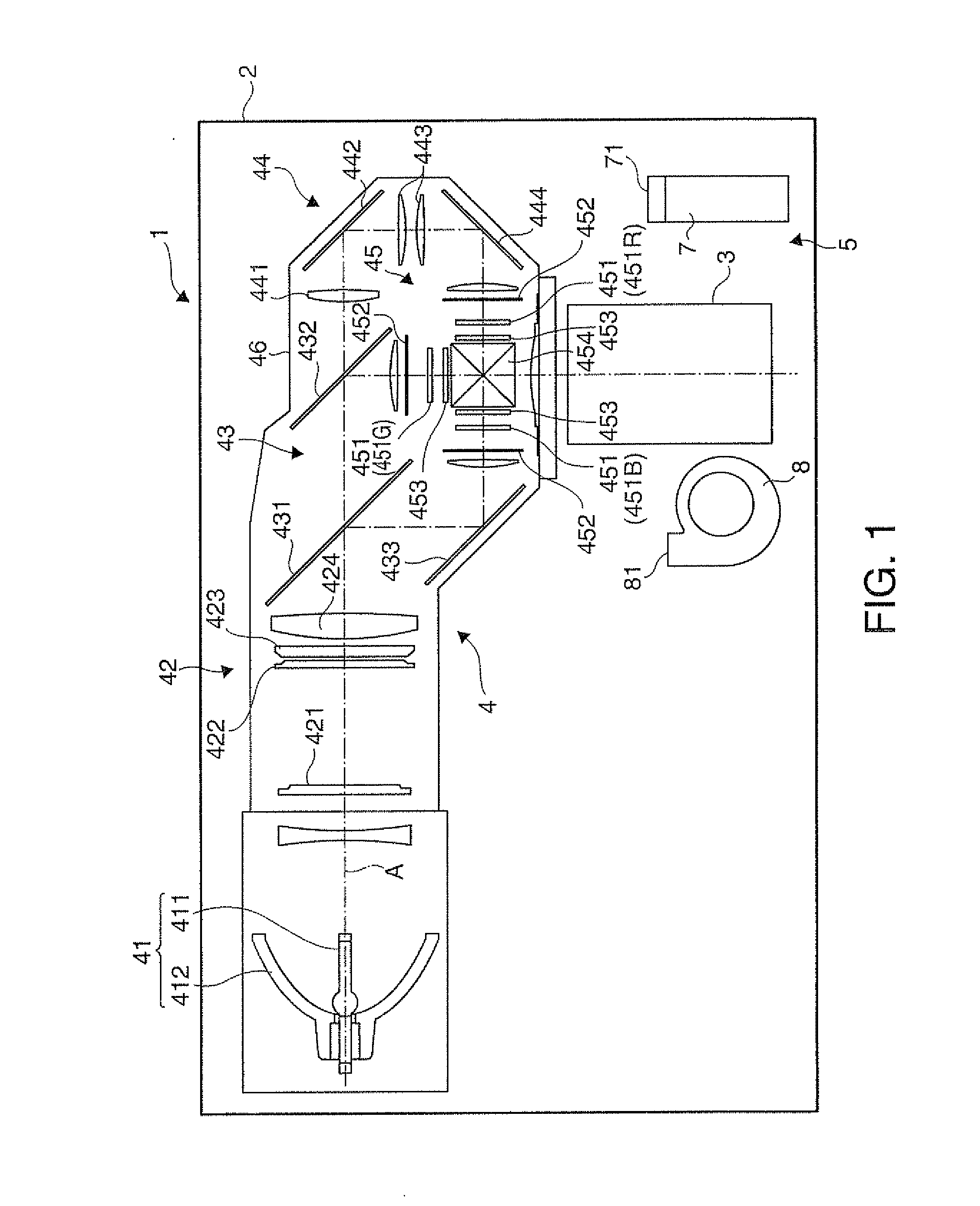
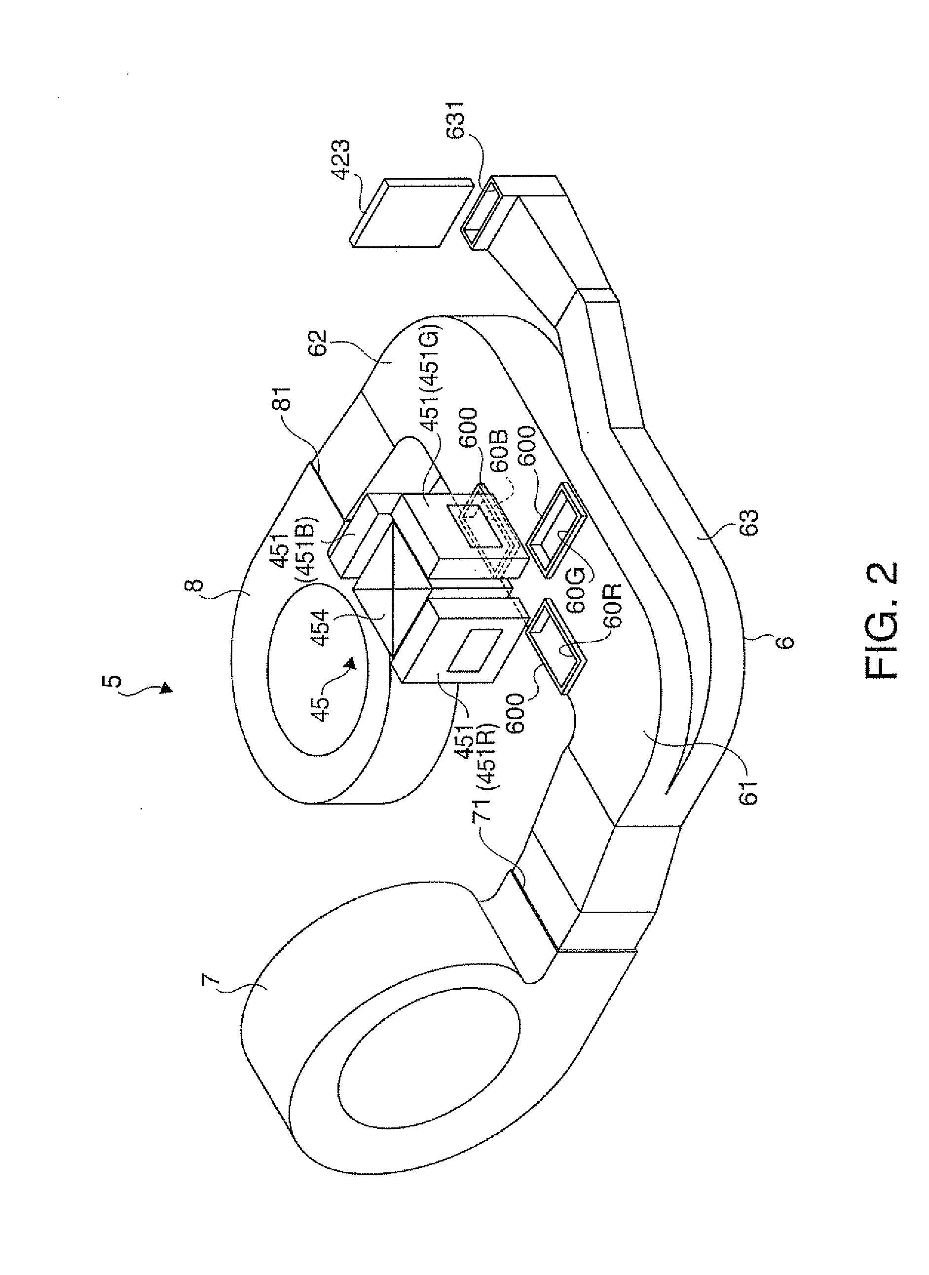
According to this embodiment, the cooling targets are cooled by the two cooling fans 7 and 8. However, the number of the cooling fans for cooling the cooling targets may be three or more.

According to this embodiment, the cooling airs A2 and B2 collide with each other at the position of the green light section cooling outlet port 60G in directions opposed to each other. However, the cooling airs A2 and B2 may collide with each other in other directions.

According to this embodiment, the cross-sectional area S of the first duct portion 61 and the second duct portion 62 is decreased in the direction toward the green light section cooling outlet port 60G by providing the inclined portion 66. However, the cross-sectional area...


PUM


Abstract

A projector includes: a cooling device which supplies cooling air to a cooling target, wherein the cooling device includes a plurality of cooling fans each of which discharges cooling air, and a plurality of ducts each one end of which is connected with the corresponding one of the plural cooling fans to introduce the cooling air toward the cooling target in directions different from each other, and the plural ducts communicate with each other at the other end and have an outlet port through which the cooling air flows out.

Description

CROSS -REFERENCEThe entire disclosure of Japanese Patent Application No. 2010-077516 filed Mar. 30, 2010 is expressly incorporated by reference herein.BACKGROUND1. Technical FieldThe present invention relates to a projector.2. Related ArtA projector which includes a cooling fan for drawing cooling air from the outside and discharging the drawn air, and a duct connected with the cooling fan for guiding the cooling air toward a light modulation device as a cooling target is known (for example, see JP-A-2005-338236).According to the technology shown in JP-A-2005-338236, one end of the duct is connected with the cooling fan, and the other end extends to the vicinity of the position of the light modulation device such that the cooling air discharged from the cooling fan can be guided toward the light modulation device. The cooling air flows out from an outlet port formed at the other end of the duct toward the light modulation device in the upward direction from below to cool the light m...

Claims


Application Information

Patent Timeline
Patent Type & Authority Applications(United States)
IPC IPC(8): G03B21/16
CPCG03B21/16
Inventor SAKAI, YOHEIKADOTANI, NORIKAZU
Owner SEIKO EPSON CORP
Why Eureka
Try Eureka