Seatbelt device and method for assembling the same

Inactive Publication Date: 2011-10-06
MAZDA MOTOR CORP
View PDF10 Cites 4 Cited by
  • Summary
  • Abstract
  • Description
  • Claims
  • Application Information

AI Technical Summary

Benefits of technology

[0004]The present invention has been devised in view of the above-described problem, and an object of the present invention to provide a seatbelt device or a method for assembling a seatbelt device which can prevent the improper concentration of the forces on the center pillar.
[0006]According to the seatbelt device of the present invention, the second retractor is fixed to the side sill which has a relatively hard rigidity and is different from the pillar to which the first retractor is fixed, so that the forces applied to the first retractor and the second retractor in the vehicle collision can be transmitted separately to both the pillar and the side sill. Thereby, the support rigidity of the seatbelt device by the vehicle body can be increased properly.
[0007]According to an embodiment of the present invention, the seatbelt device further comprises a support bracket to support the seat slide rail, wherein the support bracket is joined to the inner panel of the side sill, the specified position of the support member fixed to the inner panel of the side sill is located in back of the support bracket, and the support bracket includes a through portion to pass the lap belt which extends from the support member to the second retractor therein. Thereby, the lap belt can be provided so as to extend from the support member toward the second retractor, passing through the through portion formed at the seat slide rail. Accordingly, even if the second retractor is arranged below the seat slide rail, the lap belt can be prevented from interfering with other members.
[0009]According to another embodiment of the present invention, the second retractor comprises a lock mechanism to restrict withdrawal of the lap belt in a vehicle collision. Thereby, the withdrawal of the lap belt can be restricted by the lock mechanism in the vehicle collision, so that the passenger can be protected properly.
[0010]According to another embodiment of the present invention, the second retractor comprises a pre-tensioner to apply a tension to the lap belt when a vehicle collision is predicted. Thereby, the tension can be applied to the lap belt by the pre-tensioner of the second retractor when the vehicle collision is predicted, so that the passenger can be protected properly.
[0012]According to the method of assembling the seatbelt device of the present invention, the lap belt extending from the support member to the second tractor can be had pass in the through portion of the support bracket in case the first retractor is fixed to the pillar and the second retractor is fixed to the side sill. Accordingly, the seatbelt device can be assembled easily without any interference of the lap belt with other members.

Problems solved by technology

The seatbelt device disclosed in the above-described patent document, however, had a problem.
That is, both the retractor for shoulder belt and the retractor for lap belt are fixed to the center pillar, so that in case the lock mechanisms of the retractors operate in a vehicle collision, forces transmitting via the shoulder belt and the retractor for shoulder belt and the lap belt and the retractor for lap belt may concentrate on the center pillar improperly.

Method used


Image

  • Seatbelt device and method for assembling the same
  • Seatbelt device and method for assembling the same
  • Seatbelt device and method for assembling the same

Examples


Embodiment Construction

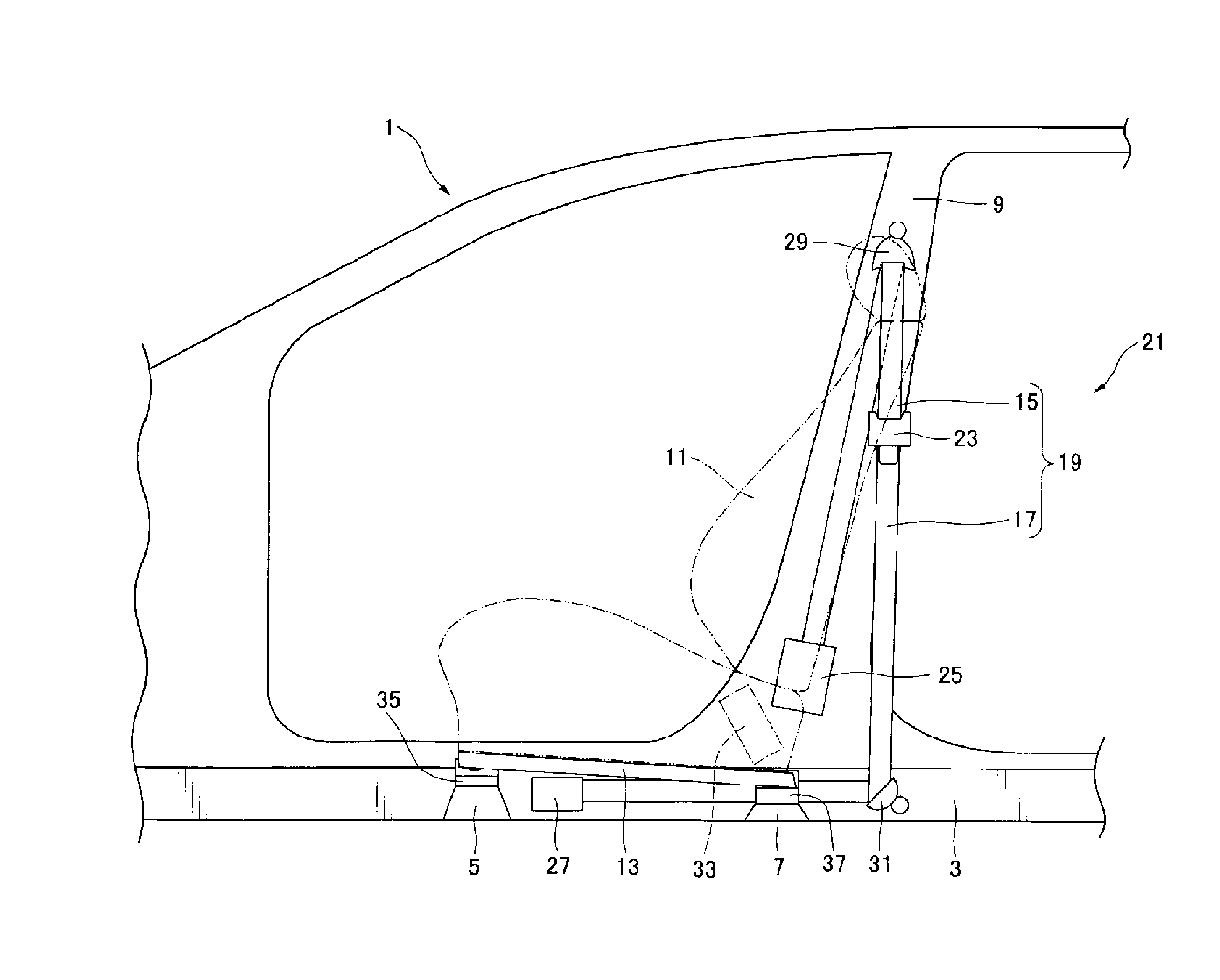
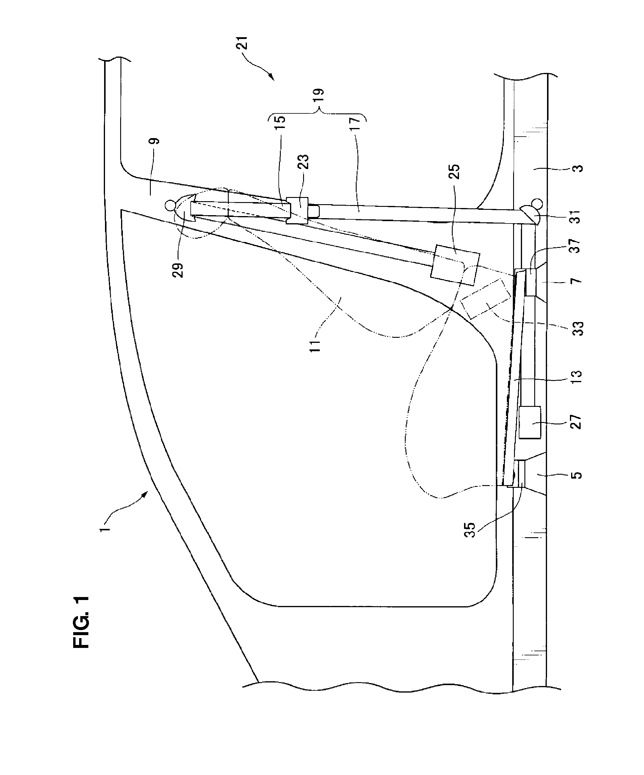
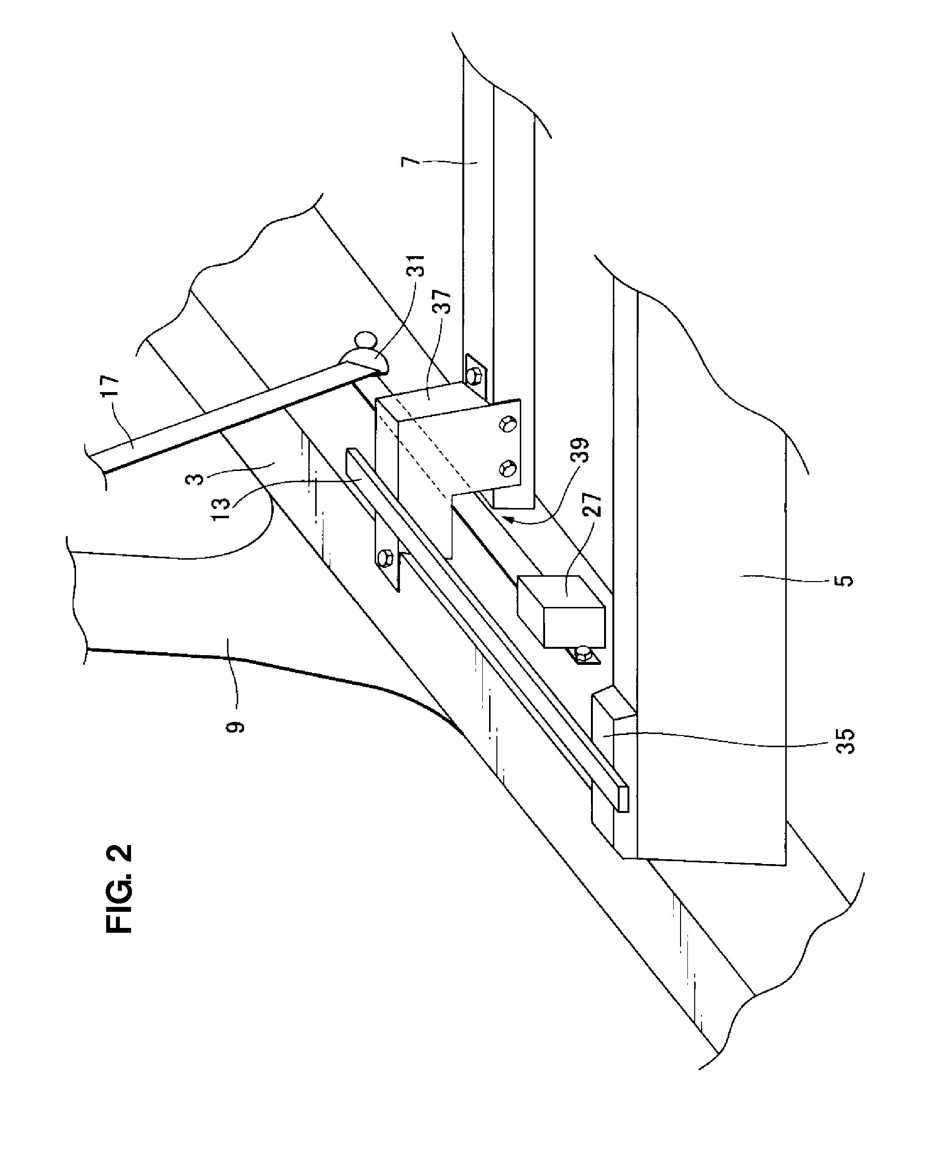
[0018]Hereinafter, a seatbelt device according to a preferred embodiment of the present invention will be descried referring to the accompanying drawings. FIG. 1 is a side view of a vehicle compartment of a vehicle equipped with a seatbelt device according to the embodiment of the present invention. FIG. 2 is a perspective view of a lower portion of the seatbelt device, when viewed from a vehicle front side.

[0019]As shown in FIGS. 1 and 2, a vehicle 1 comprises a pair of side sills 3 which extends in a vehicle longitudinal direction at its both-side end portions and is comprised of an inner panel and an outer panel which are joined, a No. 2 cross member 5 and a No. 2.5 cross member 7 which interconnect the both side sills and extend in a vehicle width direction, respectively, and a pair of center pillars 9 which extends vertically from the pair of side sills 3 at a central portion, in the vehicle longitudinal direction, of the vehicle 1. A front seat 11 for sitting of a passenger is...


PUM

PropertyMeasurementUnit
Levelaaaaaaaaaa
Tensionaaaaaaaaaa

Abstract

A seatbelt device comprises a seatbelt including a shoulder belt to restrain a passenger's upper body and a lap belt to restrain a passenger's waist portion, a tongue fixed to the seatbelt and parting the seatbelt into the shoulder belt and the lap belt, a first retractor fixed to a pillar and coupled to a tip of the shoulder belt, a second D ring attached to a position of an inner panel of a side sill below the pillar and supporting the lap belt so as to let the lap belt slide therein, and a second retractor fixed to another position of the inner panel of the side sill located in front of the second D ring and below a seat slide rail, the second retractor being coupled to a tip of the lap belt.

Description

BACKGROUND OF THE INVENTION[0001]The present invention relates to a seatbelt device and a method of assembling the same, and in particular, relates to a seatbelt device which comprises a seatbelt to which a tongue parting the seatbelt into a shoulder belt and a lap belt is fixed.[0002]Conventionally, the seatbelt device which is equipped with the tongue fixed to the seatbelt so that tensions applied to the lap belt and the shoulder belt can be adjusted separately is known as disclosed in Japanese Patent Laid-Open Publication No. 11-198757, for example. In this seatbelt device, in order to improve the amount of withdrawal and the operation of the lap belt and the shoulder belt, a retractor for lap belt with a lock mechanism is provided at a tip of the lap belt in addition to a retractor for shoulder belt with a lock mechanism which is provided at a tip of the shoulder belt. Further, according to the seatbelt device disclosed in this patent document, the retractor for shoulder belt an...

Claims


Application Information

Patent Timeline
IPC IPC(8): B60R22/00B23P11/00
CPCY10T29/49826B60R22/24
Inventor MIYAJIMA, YOICHITAKESHITA, HIROAKI
Owner MAZDA MOTOR CORP
Why Eureka
Try Eureka