
Segmented Ball Seat Assembly Valve

a technology of assembly valves and ball seats, which is applied in the direction of sealing/packing, fluid removal, borehole/well accessories, etc., can solve the problems of affecting the operation of the valve, the operator may not realize the ports are still open, and the second ball may have difficulty passing through the upper seat. , to achieve the effect of enlarge the passage diameter enough

Active Publication Date: 2011-10-06
ARTHUR KEITH MCNEILLY
View PDF3 Cites 14 Cited by
  • Summary
  • Abstract
  • Description
  • Claims
  • Application Information

AI Technical Summary

Benefits of technology

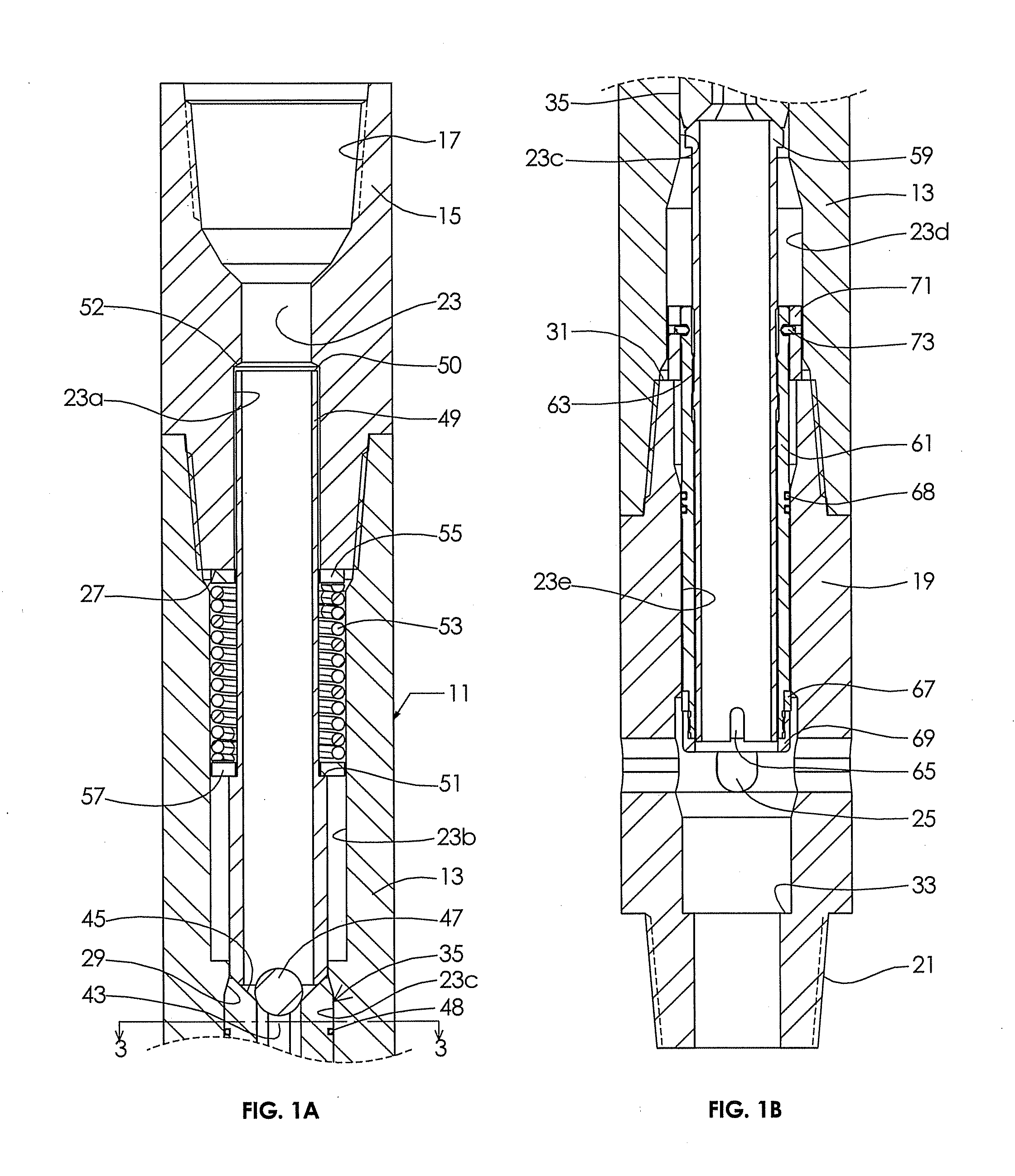
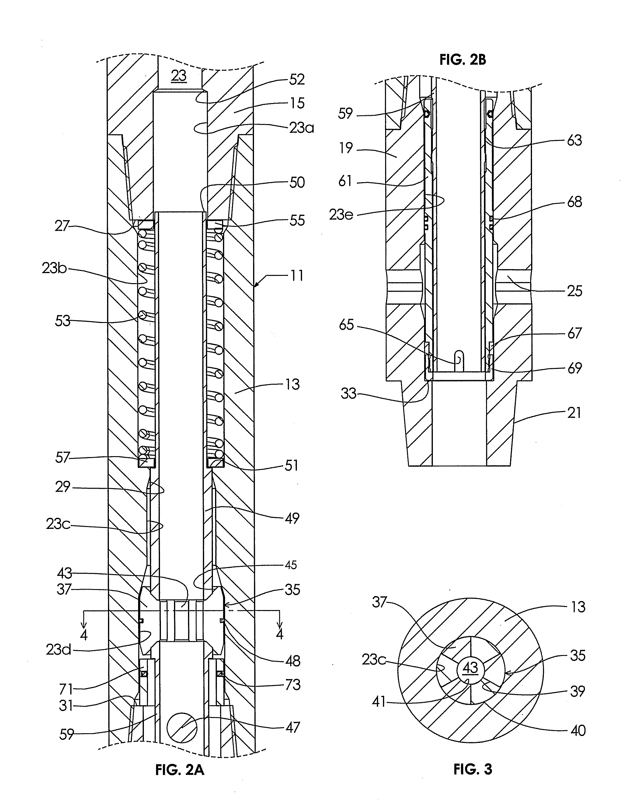
[0007]A well tool apparatus has a tubular housing having upper and lower ends for coupling into a pipe string extending into a well. The housing has an axially extending bore with an enlarged diameter portion. A seat assembly is mounted in the bore in a first position above the enlarged diameter portion for receiving a drop member, such as a ball, conveyed down the pipe string. The seat assembly has a passage therethrough that is blocked by the drop member after the drop member lands on the seat assembly. A retainer retains the seat assembly in the bore above the enlarged diameter portion. The retainer allows the seat assembly to move downward from the first position to a second position in the enlarged diameter portion in response to a selected fluid pressure applied in the bore above the seat assembly after the drop member has landed on the seat assembly. The seat assembly is radially expansible while in the enlarged diameter portion so as to enlarge a diameter of the passage sufficiently to allow the drop member to pass through the passage.
[0011]In the embodiment shown, a downward facing shoulder is located in the bore against which an upper portion of the seat assembly abuts while in the first position. The downward facing shoulder prevents upward movement of the seat assembly in the bore from the first position, but allows downward movement of the seat assembly to the second position.

Problems solved by technology

Otherwise, an operator might not realize the ports are still open and begin pumping cement down the pipe string.
However, if a second ball has to pass through the upper seat after it has broken away, problems can occur.
The second ball may have difficulty passing through the upper seat after it has broken away, requiring greater pressure force.
Additionally, if the sliding sleeve travel is impeded, the ball can possibly be forced though the yieldable seat assembly without fully closing the sleeve.

Method used


Image

  • Segmented Ball Seat Assembly Valve
  • Segmented Ball Seat Assembly Valve
  • Segmented Ball Seat Assembly Valve

Examples


Embodiment Construction

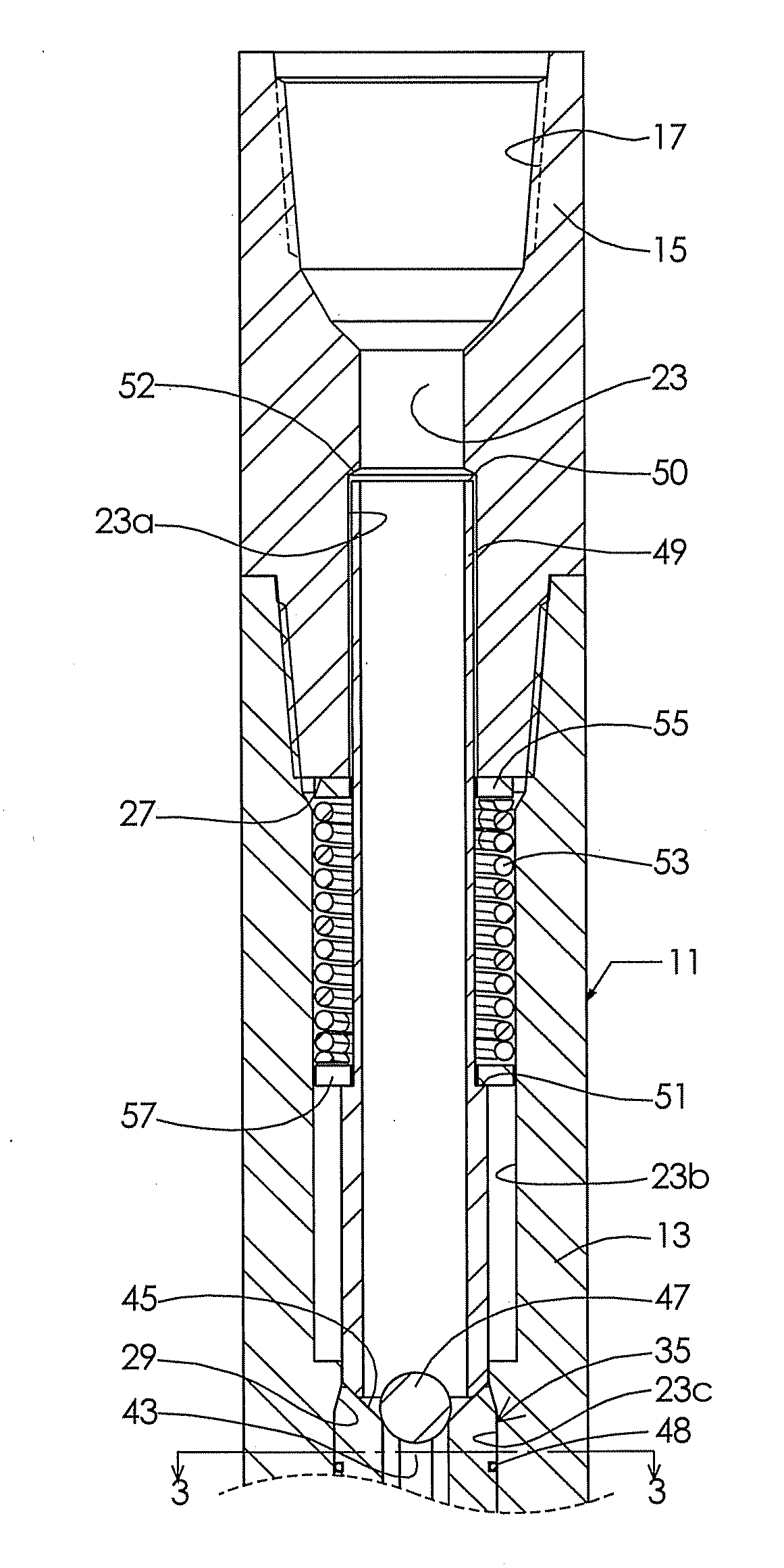
[0019]Referring to FIGS. 1A and 1B, valve assembly 11 has a tubular housing 13. Housing 13 includes an upper adapter 15 secured by threads to the upper end of a central portion of housing 13. Upper adapter 15 has internal threads 17 for securing to a string of well pipe (not shown). In this example, the well pipe comprises drill pipe, but it could be other types of pipe, including tubing, casing and liner pipe. Housing 13 also includes a lower adapter 19 secured by threads to a lower end of the central portion of housing 13. Lower adapter has external threads 21 for securing to a string of well pipe.

[0020]A bore 23 extends axially through housing 13, including adapters 15 and 19. Bore 23 has an upper portion 23a within upper adapter 15 and an intermediate portion 23b of larger diameter in the central portion of housing 13. A receptacle portion 23c of smaller diameter than intermediate portion 23b joins and is located below intermediate portion 23b. An enlarged bore portion 23d of di...


PUM


Abstract

The segmented ball seat valve is an annular communication valve normally installed in a string of pipe that is to be deployed to a depth within a well. The segmented ball seat valve provides communication between the inside of the pipe and the well bore or casing through open ports. The segmented ball seat valve can be closed to shut off communication by dropping / pumping a ball to the segmented ball seat valve and applying pressure to close the valve. The application of pressure causes the ball seat assembly to move downward into an enlarged portion of the bore. The segments of the seat assembly move outward in the enlarged area to permit passage of the ball.

Description

CROSS-REFERENCE TO RELATED APPLICATION[0001]This application claims priority to provisional application Ser. No. 61 / 320,958, filed Apr. 5, 2010.FIELD OF THE INVENTION[0002]This invention relates generally to downhole oil and gas well equipment and in particular to a seat assembly mounted in well pipe that receives a ball or the like dropped down the pipe from the surface, the seat assembly being movable to perform a function upon the application of fluid pressure after the ball has landed.BACKGROUND OF THE INVENTION[0003]A technique employed in oil and gas well drilling, completion and workover operations involves dropping or pumping a sealing member down the well pipe onto a seat assembly. The sealing or drop member is typically a ball or dart. After the drop member lands on the seat assembly, it forms a seal, allowing the operator to apply increased fluid pressure in the well pipe above the seat assembly. A shear member shears, allowing the seat assembly to move downward to perfor...

Claims


Application Information

Patent Timeline
IPC IPC(8): E21B33/12
CPCE21B34/14E21B34/142
Inventor MCNEILLY, ARTHUR KEITH
Owner ARTHUR KEITH MCNEILLY
Learn More