
Gas driven rotation motor, a tool provided with a gas driven rotation motor and a method for regulating speed of a gas driven rotation motor

a technology of rotating motor and gas driven motor, which is applied in the direction of power-driven tools, machines/engines, manufacturing tools, etc., can solve the problems of mechanical speed governors not operating properly, affecting the operation of grinding tools in this way, etc., and achieves less complex construction and less cost.

Active Publication Date: 2011-09-29
ATLAS COPCO INDAL TECHN AB
View PDF5 Cites 8 Cited by
  • Summary
  • Abstract
  • Description
  • Claims
  • Application Information

AI Technical Summary

Benefits of technology

The present invention provides a gas driven rotation motor with a simplified construction and lower cost compared to prior art. The motor includes a speed governor for controlling the pressure gas inlet flow, which is coupled to the rotor through a set of pins. The motor also includes a spring arrangement for secure frictional contact between the outer race, inner race, rolling elements, and the pins of the coupling device. The motor can be used in a tool for rotating an implement. The invention offers a safe-failure design for the speed governor, which is a critical component of the motor.

Problems solved by technology

Breaking up of the grinding tool in this way would be very hazardous for the operator and other people and equipment in the vicinity of the tool in operation.
There is a particular problem to have mechanical speed governors operate properly at high speed motors like turbines.

Method used


Image

  • Gas driven rotation motor, a tool provided with a gas driven rotation motor and a method for regulating speed of a gas driven rotation motor
  • Gas driven rotation motor, a tool provided with a gas driven rotation motor and a method for regulating speed of a gas driven rotation motor
  • Gas driven rotation motor, a tool provided with a gas driven rotation motor and a method for regulating speed of a gas driven rotation motor

Examples


Embodiment Construction

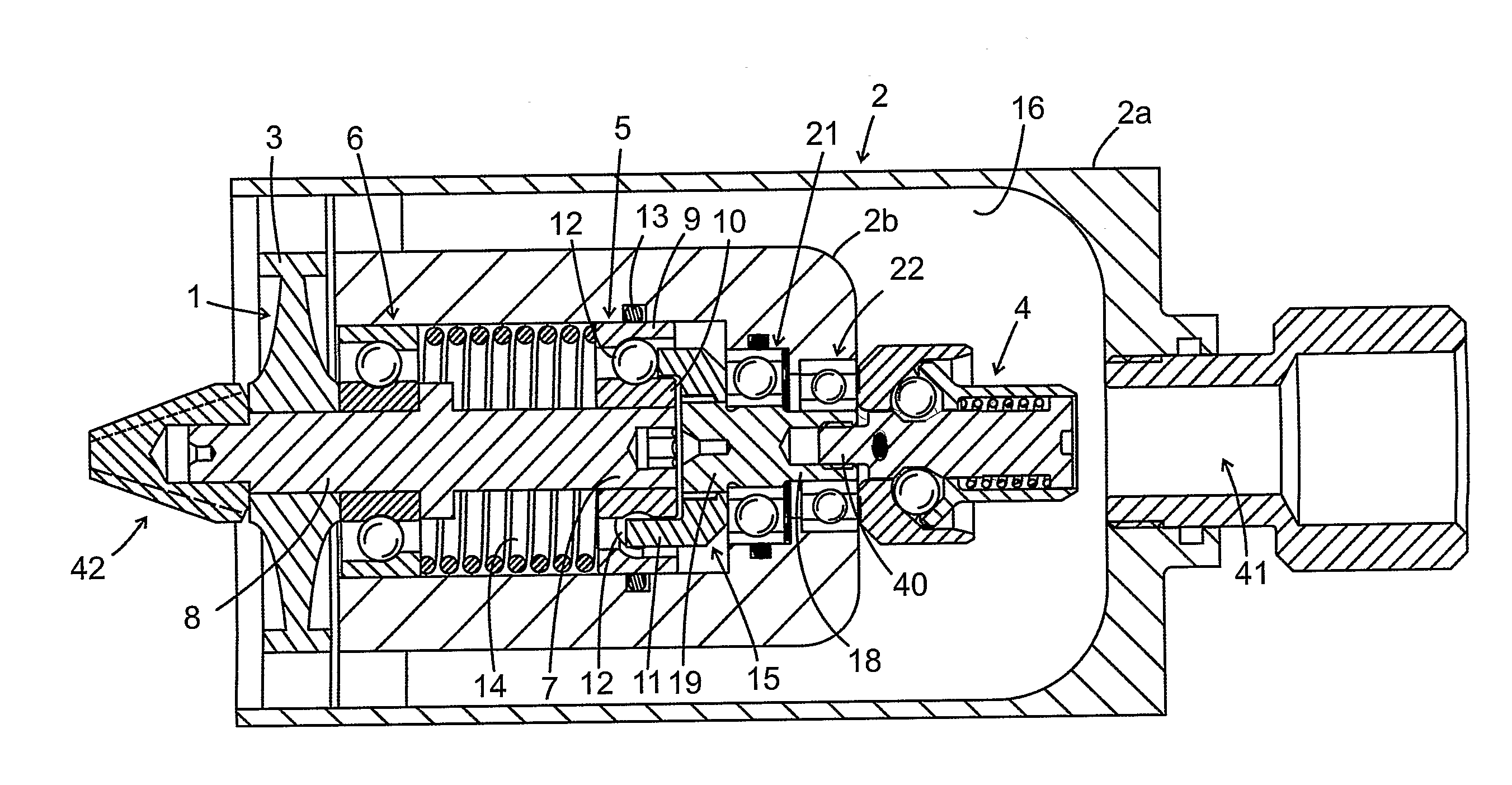
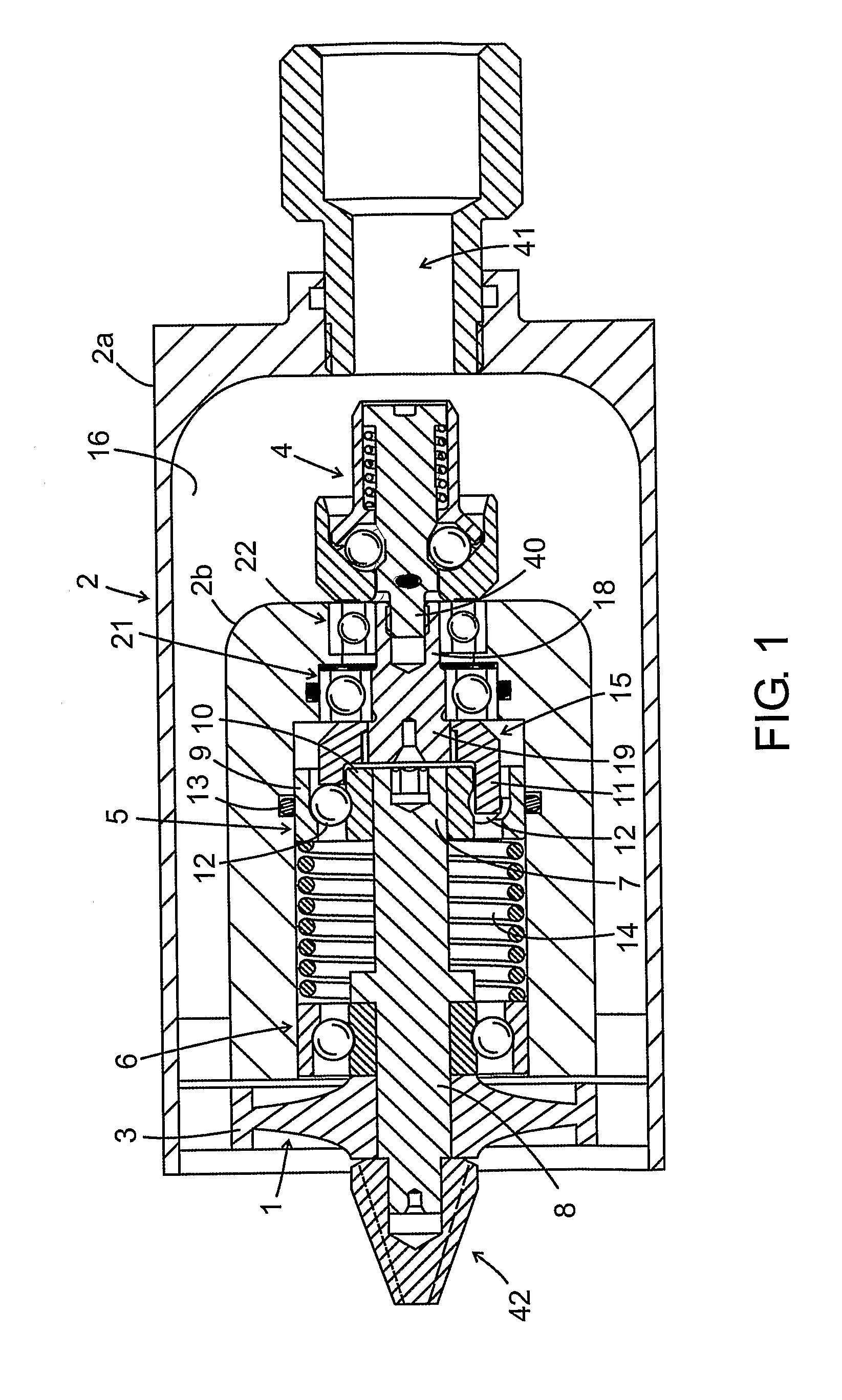
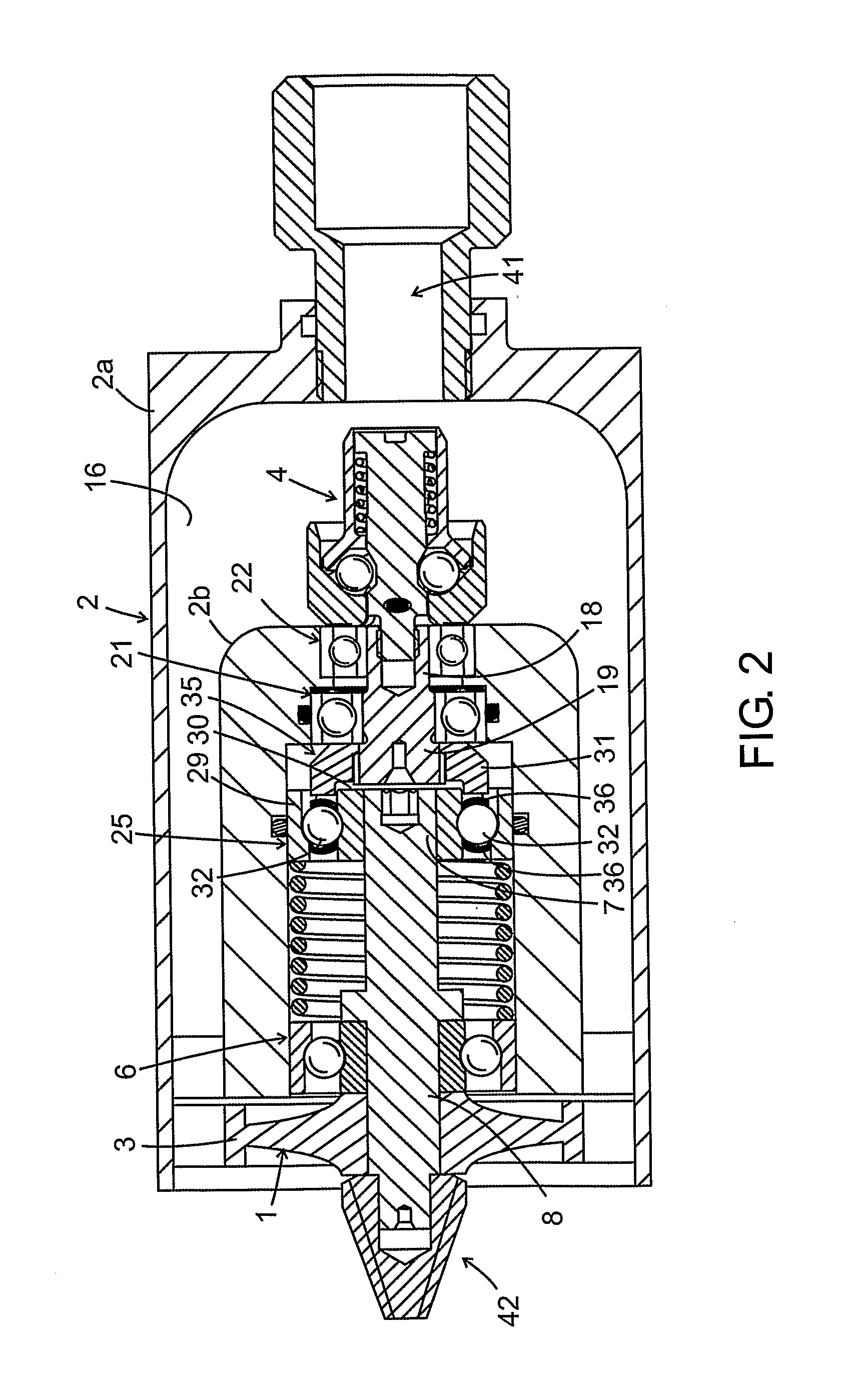
[0020]In FIG. 1 is schematically shown a gas driven or pneumatic rotation motor. The rotation motor comprises a rotating member 1 arranged in a housing 2. A pressure gas, e.g. air, is supplied to the housing via a pressure gas inlet 41 and the rotating member is driven to rotate by the supplied pressure gas. In the illustrated example, the rotation motor is a turbine motor with a rotor 3, but the invention is not limited to turbine motors, for example the motor could also be a vane motor. Furthermore, the motor comprises a rotatable speed governor 4 for regulating the inflow of pressure gas to the rotating member, and a coupling device 15. The speed governor can be of a previously known type, as explained earlier, with a movable part that can move into the pressure gas inlet 41. The rotating member 1 comprises a rotor 3 and a rotor shaft 7,8 carrying the rotor and being journalled in the housing 2 by means of two ball bearings 5, 6. In this connection, it should be mentioned that in...


PUM


Abstract

A gas driven motor includes a housing, a gas driven rotating member including a rotor and a rotor shaft carrying the rotor and journalled in a first bearing and a second bearing supported in the housing, and a speed governor for controlling a pressure gas inlet flow in response to the rotation speed of the rotating member. The first bearing includes a set of rolling elements, an outer race arranged in the housing and an inner race arranged on a shaft portion of the rotating member, the set of rolling elements being in contact with the races on which the rolling elements roll. The motor further includes a coupling device arranged to couple the speed governor to the rolling elements of the first bearing, thereby transferring the rotary motion from the rolling elements to the speed governor.

Description

BACKGROUND OF THE INVENTION[0001]The present invention relates to a gas driven rotation motor, a tool provided with a gas driven rotation motor and a method for regulating the rotation speed of a gas driven rotation motor.[0002]Gas driven rotation motors, or pneumatic motors, are used in machines with rotating tools such as grinding machines, milling machines, drilling machines, etc. In particular, gas driven rotation motors are used in portable power tools and hand held power tools for a number of different applications including construction, manufacturing, dental machines, artists' works etc.[0003]Vane motors and turbine motors are the most common types of gas driven or pneumatic motors. In the turbine motor the rotation speed is considerably higher than in the vane motor. For both types of motors, speed governors are used to regulate the inflow of air, or other gas if such is used, to the motor and thereby limiting to a maximum the rotation speed at idle running. It is particula...

Claims


Application Information

Patent Timeline
Patent Type & Authority Applications(United States)
IPC IPC(8): F01D17/06B25F5/00
CPCF01C13/02F01C20/08F01C21/02F05D2270/02F04C2240/51G05D13/10F01D15/062B24B55/00
Inventor NELSON, ANDERS URBANOLSSON, STEN HERMAN
Owner ATLAS COPCO INDAL TECHN AB
Learn More