
Providing a transverse filling inside and elongated narrow cavity

a transverse filling and elongated technology, applied in the direction of containers, applications, sacks, etc., can solve the problems of affecting affecting the performance of the work, and requiring expensive equipment and/or long time, so as to achieve the effect of compromising the structural properties of the wing

Inactive Publication Date: 2011-09-22
LM GLASSFIBER
View PDF8 Cites 9 Cited by
  • Summary
  • Abstract
  • Description
  • Claims
  • Application Information

AI Technical Summary

Benefits of technology

[0013]It is the object of the invention to indicate a method for performing different operations inside a wing for a wind power plant, where these operations may be performed without dismounting a wing blade, without making the process time-consuming, and without compromising the structural properties of the wing.DESCRIPTION OF THE INVENTION
[0019]In a preferred variant of a method according to the invention, the method further includes a step wherein an additional material layer is laid upon the first material layer, where the additional material has a specific density and / or strength which is greater than that of the material laid at first. This variant is particularly preferred as this second material layer may have strength, elasticity or other properties providing the desired effect. At the same time, it is necessary with a light material for providing a bearing base for applying the second and heavier material. Particularly this function is fulfilled by the expanding foam laid at first. The subsequent material layer may e.g. be a polyurethane rubber mass which is laid in a layer with appropriate thickness. The thickness may be in an interval of a few centimetres to e.g. 60 or 70 centimetres or more. By laying a give amount of material on a well-defined area and by using a defined application procedure, a very exact laying can be achieved, e.g. by a self-levelling material without having to monitor the laying process itself. One may advantageously suffice with e.g. performing inspection after finishing application of material.
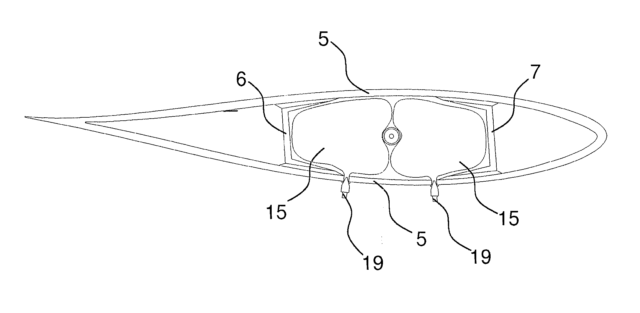
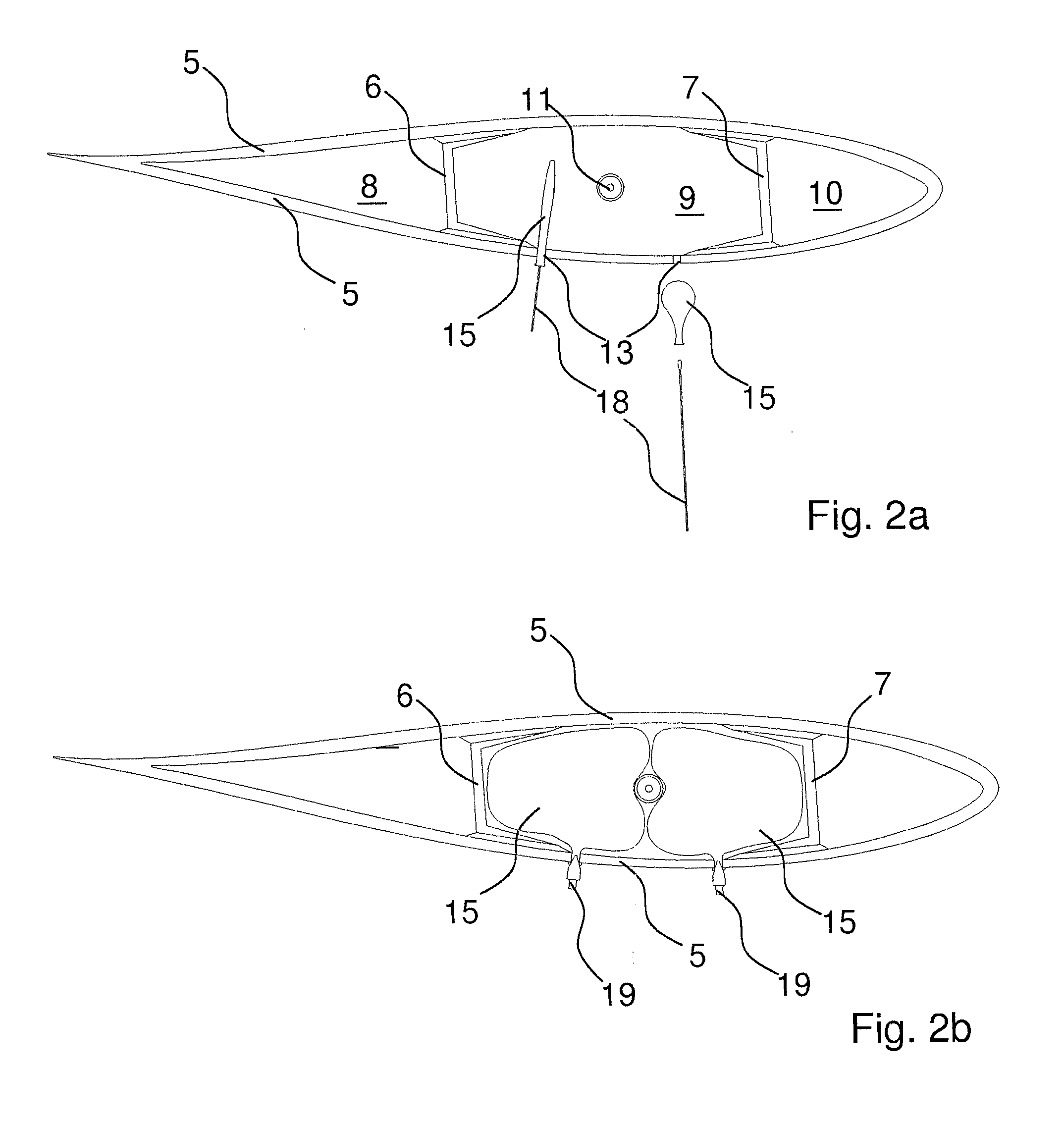
[0020]As mentioned previously, by the method according to the invention balloon or balloons are mounted through a mounting hole, where the balloon is preferably mounted by means of a long slender tool whereby the balloon e.g. can be extended and passed through the mounting hole. It may be a long rod, possibly with a rounded end, which is passed into the balloon through its neck. By pressing the tool down into the balloon, the balloon is stretched and may be passed more easily through the small mounting hole in the side of the wing blade. In this way, the required hole size may be minimised.
[0024]Another variant of a method according to the invention is that the method is used for forming a reinforcement in an area of a wing blade for a wind power plant. This may be an advantage if it appears that a certain type of wing blades have problems with bulges or similar in a certain area. The invention may then typically be used for delimiting a certain area of the interior of the wing and subsequently fill this area with either expanding polyurethane foam or another material which may prevent the bulging by reinforcing the actual area on the wing blade.
[0026]A balloon for use in connection with a method according to the invention may be provided with a valve, preferably a valve preventing e.g. air from flowing out of the balloon, where the valve e.g., is of the type known from bicycles and cars. By using such a valve, commonly available equipment may be used for pumping air into the balloon as well as for regulating and supervising how great pressure is present in the balloon. Inflation may e.g. be effected by a hand pump or a battery-driven handheld pump. After performing the required task, the air may easily be let out of the balloon, and it may possibly be drawn out of the mounting hole or pushed back through the mounting hole completely into the wing blade, after which mounting holes and inspection holes are sealed in a suitable way.
[0027]In a preferred variant of a balloon according to the invention, this is provided with a balloon neck which substantially has a length corresponding to the material thickness of the wing shell or longer. In that way, it is easier to mount and to ensure that the balloon is in the proper place. By mounting a clip or similar on the balloon neck at the valve it may be ensured that the balloon remains in proper position until it is filled with a suitable amount of air.

Problems solved by technology

If such a fitting is broken, oscillations and loads may easily arise in the central pipe, and further damage may easily appear.
Common to the prior art method is, however, that they require dismounting of the wing, and that expensive equipment and / or long time is needed for performing the work required immediately before and after performing the primary task.

Method used


Image

  • Providing a transverse filling inside and elongated narrow cavity
  • Providing a transverse filling inside and elongated narrow cavity
  • Providing a transverse filling inside and elongated narrow cavity

Examples


Embodiment Construction

[0014]As mentioned in the introduction, the invention concerns a method for performing a retrofit task whereby is formed at least one barrier transversely of at least one elongated channel. This method may advantageously include at least the following steps: establishing a number of inspection and mounting holes in the shell, preferably small, drilled holes with a diameter between 8 and 25 millimetres and preferably with a diameter between 10 and 12 millimetres; providing one or more inflatable balloons in the channel in question, where a balloon is passed through one of the established holes; inflating or filling the balloon or balloons, preferably with atmospheric air; and applying at least one first material layer which extends between the sidewalls of the elongated channel and across the balloon or balloons, where the layer preferably is expanded polyurethane foam.

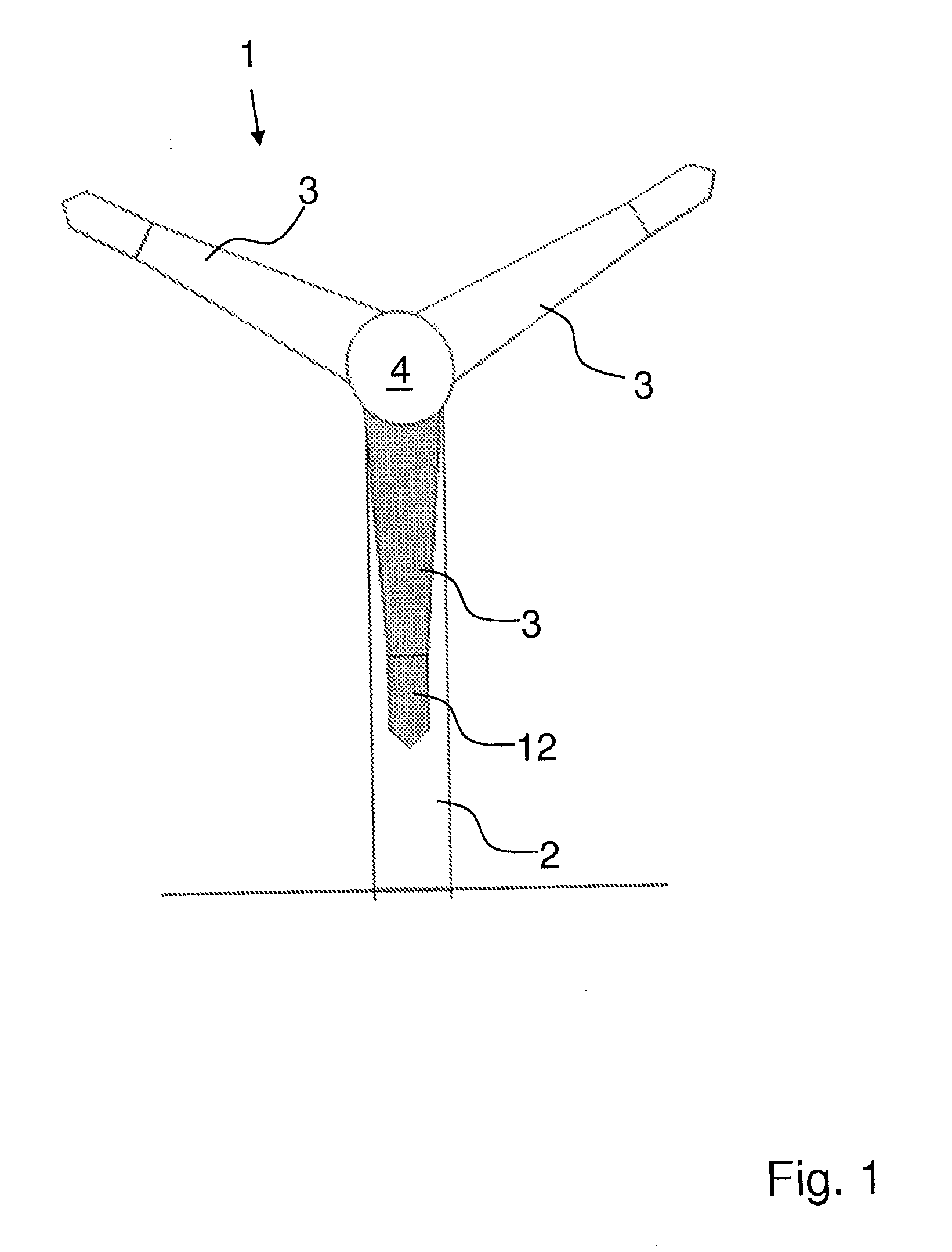
[0015]In the following, the invention will be described in relation to a task which may be performed on an existing ...


PUM

PropertyMeasurementUnit
diameteraaaaaaaaaa
diameteraaaaaaaaaa
diameteraaaaaaaaaa

Abstract

A method for performing a task in a tight place in an elongated profile, preferably in a wing blade with an outer shell for a wind power plant, whereby at least one barrier is formed transversely of at least one elongated channel in the profile and a balloon for use in performing the task. The method may include the following steps: establishing a number of inspection and mounting holes in the surface of the shell, mounting at least one inflatable balloons in the at least one channel, filling the balloon(s) with air, and applying at least one first material layer between the sidewalls of the elongated channel and across the balloon(s), the layer preferably being expanding polyurethane foam. The applied layer of material fills cracks and gaps between balloons and wing parts, providing a load-bearing layer between these parts. An additional layer may subsequently be laid upon the former layer.

Description

BACKGROUND OF THE INVENTION[0001]1. Field of the Invention[0002]The present invention concerns a method for performing a task in a tight place in an elongated profile, preferably in a wing blade with an outer shell for a wind power plant, where the task preferably is a retrofit task whereby is formed at least one barrier transversely of at least one elongated channel in the profile. The invention further includes a balloon for use by the task.[0003]2. Description of Related Art[0004]In connection with wing blades for wind power plants, where the wings typically are made of a fibre composite material, such as glass fibre reinforced plastic or similar, there may sometimes be a need for making various repairs, modernisations or preventive measures, which in the following are all expressed by a common term, namely retrofit.[0005]In connection with a retrofit task internally of a wing blade, often serious problems may arise since performing an even minor retrofit task far into a wing is ...

Claims


Application Information

Patent Timeline
Patent Type & Authority Applications(United States)
IPC IPC(8): B23P11/00B65D30/24
CPCB29C44/184F03D1/003F05B2230/80Y10T29/49826F05B2250/36Y02E10/721F05B2240/98F03D80/50Y02E10/72Y02P70/50
Inventor OKUTAN, UFUK
Owner LM GLASSFIBER
Learn More