Methods, systems and apparatus for jointly optimizing node locations and corresponding output values of a color look-up-table (LUT)

a color look-up and output value technology, applied in the field of color image processing, can solve the problems of not matching the red described in the rgb space and displayed on the video monitor, and no known attempt to simultaneously optimize the node location and valu

Inactive Publication Date: 2011-09-15
XEROX CORP
View PDF12 Cites 22 Cited by
  • Summary
  • Abstract
  • Description
  • Claims
  • Application Information

AI Technical Summary

Benefits of technology

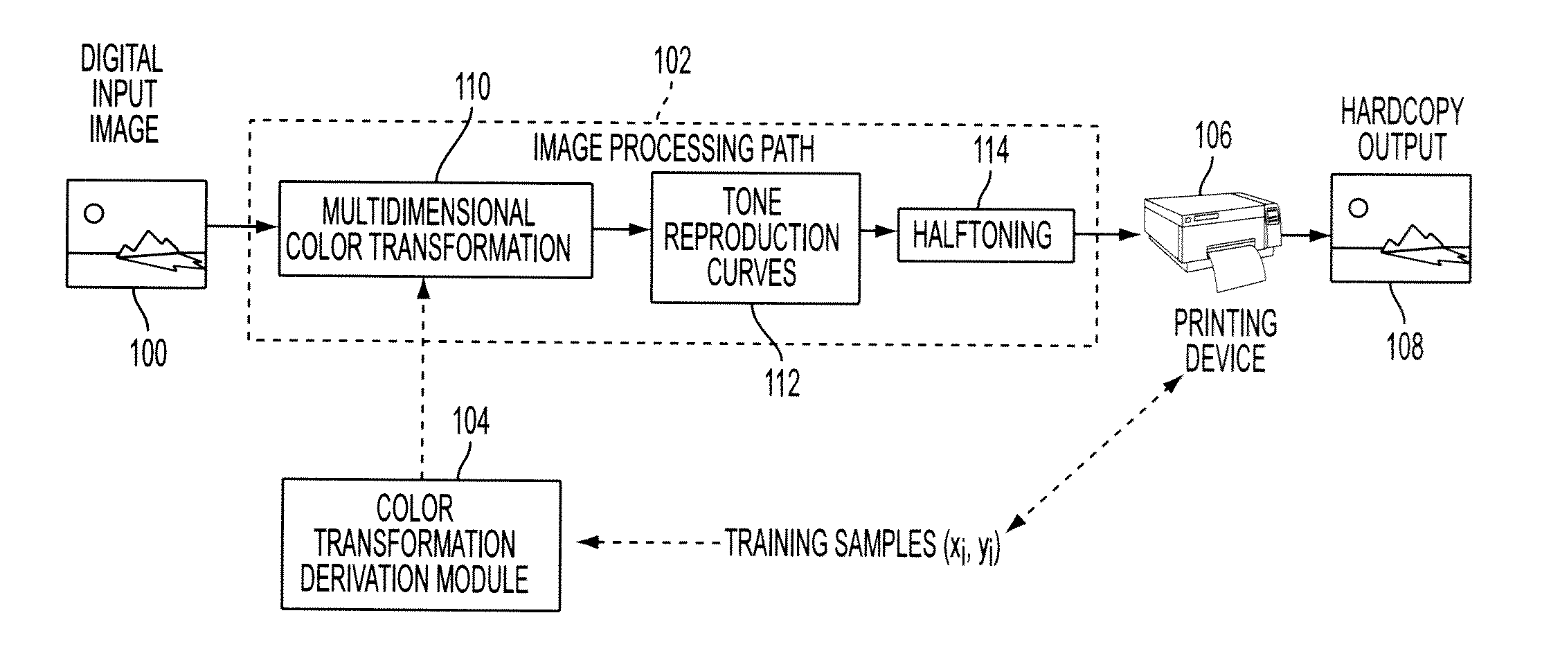
[0015]In one embodiment of this disclosure, described is a method of generating a multidimensional LUT (look-up-table) representing a color transformation function associated with an imaging device, the method comprising a) generating a set of LUT node locations by solving a first optimization problem to minimize a first defined error criterion calculated over a set of training samples associated with the color transformation function; and b) generating a set of LUT node values associated with their respective LUT node locations by solving a second optimization problem to minimize a second defined error criterion calculated over the set of training samples, the second error criterion accounting for one or more interpolation processes associated with determining LUT values at LUT non-nodal locations.
[0016]In another embodiment of this disclosure, described is a printing apparatus comprising an image marking device; a controller operatively connected to the image marking device, the controller configured to access a multidimensional LUT representing a color transformation function associated with rendering an image on the image marking device, wherein the multidimensional LUT is generated by a process comprising a) generating a set of LUT n ode locations by solving a first optimization problem to minimize a first defined error criterion calculated over a set of training samples associated with the color transformation function; and b) generating a set of LUT node values associated with their respective LUT node locations by solving a second optimization problem to minimize a second defined error criterion calculated over the set of training samples, the second error criterion accounting for one or more interpolation processes associated with determining LUT values at LUT non-nodal locations.

Problems solved by technology

As a result, the visual appearance of the red described in RGB space and displayed on the video monitor will usually not match that of the red described in CMYK space and printed on a page.
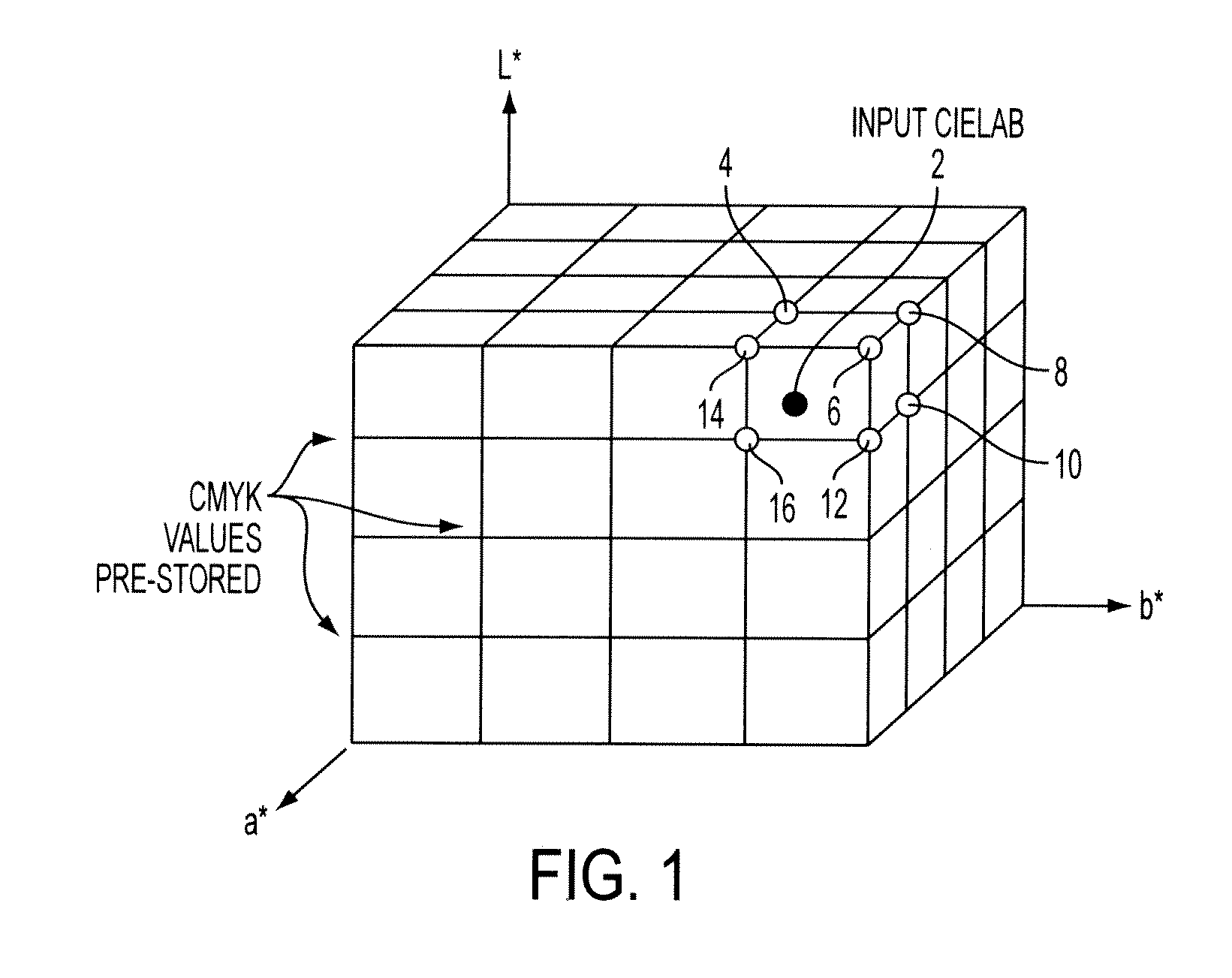
Color transformations are often complex, multidimensional functions that correct for the nonlinear behavior of both digital color devices and the human visual system, which would require a significant amount of memory in order to process large images in real-time.
However the size of a LUT is typically limited by the amount of available processor RAM and cache memory.
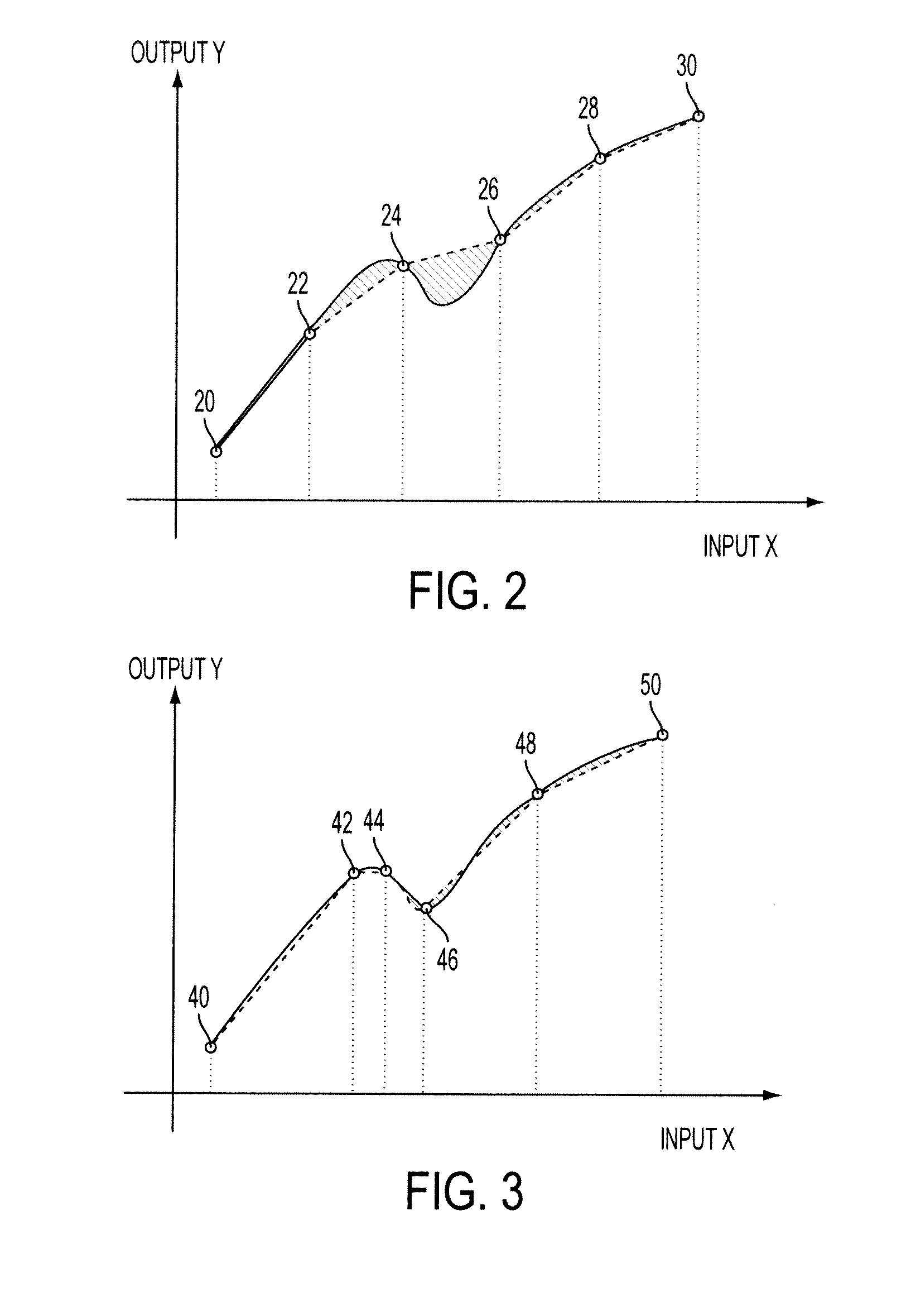
More sophisticated techniques attempt to adapt node locations to transform characteristics such as transform curvature, however no known attempt has been made to simultaneously optimize node locations and values.

Method used


Image

  • Methods, systems and apparatus for jointly optimizing node locations and corresponding output values of a color look-up-table (LUT)
  • Methods, systems and apparatus for jointly optimizing node locations and corresponding output values of a color look-up-table (LUT)
  • Methods, systems and apparatus for jointly optimizing node locations and corresponding output values of a color look-up-table (LUT)

Examples


embodiment 1 (fig.7)

Embodiment 1 (FIG. 7): Sequential Optimization of Node Location and ValuE (SOLVE)

[0057]Step 1: Using a training set, estimate the curvature of the transform and optimize node locations using a greedy technique which allocates more nodes in regions of higher transform curvature. (For example, the SSD algorithm in Monga et al., “INPUT-ADAPTIVE METHOD FOR COLOR TABLE LOOKUP,” U.S. Patent Application Publication No. 2009 / 0067017, published Mar. 12, 2009.) Let Xnd* denote the optimized node locations.

[0058]Step 2: For fixed node locations Xnd*, solve for the best output node values ynd* by minimizing the squared error:

∥ytr−WXnd*·ynd∥2.

[0059]For T>M, this is a well-posed convex problem with the minimizer given by:

ynd*=(WXnd*·TWXnd*)−1(WXnd*)T ytr

[0060]Note that the interpolation or weight matrix WXnd* is determined uniquely as the set of nodes Xnd* is known.

[0061]End: Xnd* and ynd* are determined as the node locations and output values respectively.

embodiment 2 (fig.8)

Embodiment 2 (FIG. 8): REpeated—Sequential Optimization of Node Location and ValuE (RESOLVE)

[0062]Step 1: Initialization—same as Step 1 of the SOLVE algorithm.

[0063]Step 2: For fixed node locations Xnd*, solve for the best output node values ynd* by minimizing

∥ytr−WXnd*·ynd∥2.

[0064]For T>M, this is a well-posed convex problem with the minimizer given by:

ynd*=(WXnd*·TWXnd*)T ytr.

[0065]Note that the interpolation or weight matrix WXnd* is determined uniquely as the set of nodes Xnd* is known.

[0066]Step 3: Based on the optimized vector of node output values ynd* in Step 2, optimize WXnd so as to minimize the cost function in Eqn (3).

[0067]The optimization is carried out subject to the following constraints:[0068]Selection constraint: wiTei=0, wi ∈ RM—ith row of W, ei—membership vector[0069]Non-negativity: wij≧0, i=1,2, . . . , T, j=1,2, . . . . , M.[0070]Interpolation constraint : WXnd·1=1, where 1 ∈ RM is a vector of all 1's.

[0071]The first constraint guarantees that any training poin...


PUM


Abstract

This disclosure provides methods, systems and apparatus for jointly optimizing node locations and corresponding output value of a color look-up-table (LUT) associated with an imaging device. According to one exemplary method, initially a set of LUT node locations are generated by solving a first optimization problem and subsequently, a set of LUT node values are generated by solving a second optimization problem.

Description

BACKGROUND[0001]This disclosure relates to the art of color image processing, more specifically, the presently disclosed methods, systems and apparatus provide for the selection of node locations and associated node values for a multi-dimensional color transformation LUT, based upon a joint optimization approach.[0002]An image prepared for rendering on an electronic device is represented by a set of pixels that each describes a small portion of the image in terms of digital values that represent the colorants available to the rendering device. For example, in an image prepared for display on a video monitor, each pixel typically describes the intensity of the red (R), green (G) and blue (B) components of light that are illuminated to reproduce the color at the associated region of the screen. Similarly, in an image prepared for rendering on a printing device operating in a CMYK color space, each pixel describes the amount of cyan (C), magenta (M), yellow (Y) and black (K) colorants ...

Claims


Application Information

Patent Timeline
Patent Type & Authority Applications(United States)
IPC IPC(8): H04N1/60G06K9/00
CPCH04N1/6025
Inventor MONGA, VISHALBALA, RAJA
Owner XEROX CORP
Why Eureka
Try Eureka