
Near real time optical phase conjugation

Active Publication Date: 2011-09-15
BIO RAD LAB INC
View PDF65 Cites 4 Cited by
  • Summary
  • Abstract
  • Description
  • Claims
  • Application Information

AI Technical Summary

Benefits of technology

[0008]In some embodiments, the conjugate beam is of higher power than the scattered light. The conjugate beam may be directed toward the translucent medium for a longer time than is required to generate and digitally record the numerical representation of the interference pattern. The method may further comprise turning off the sample illumination beam and the reference beam when the conjugate beam is directed toward the translucent medium. In some embodiments, the light scattered by the medium comprises light traveling in generally the same direction as the sample illumination beam. In some embodiments, the light scattered by the medium comprises light reflected from the medium. Generating the conjugate beam having the computed characteristics may include generating the conjugate beam using a single light modulating device. Generating the conjugate beam having the computed characteristics may include generating the conjugate beam using two synchronized modulation devices.
[0009]In some embodiments, the translucent medium is biological tissue, and the method further comprises tagging particular structures within the biological tissue so that the tagged structures preferentially scatter more light than is scattered by untagged surrounding tissue, and consequently are more intensely illuminated by the conjugate beam than is the untagged surrounding tissue. Tagging particular structures may comprise tagging cancer cells. The method may further comprises irradiating, via the conjugate beam, the tagged cancerous cells with doses of

Problems solved by technology

Turbid or translucent media present special problems for optical systems.
For example, a medium such as biological tissue may transmit light efficiently, but may scatter the light substantially so that it is difficult to see or image through the tissue or to direct light through the tissue to a particular target.
The difficulty is not primarily due to the absorption of light by the sample, but to the scattering that interferes with conventional image formation.
A disadvantage of prior systems is that the recording of the hologram may take several minutes.

Method used


Image

  • Near real time optical phase conjugation
  • Near real time optical phase conjugation
  • Near real time optical phase conjugation

Examples


Embodiment Construction

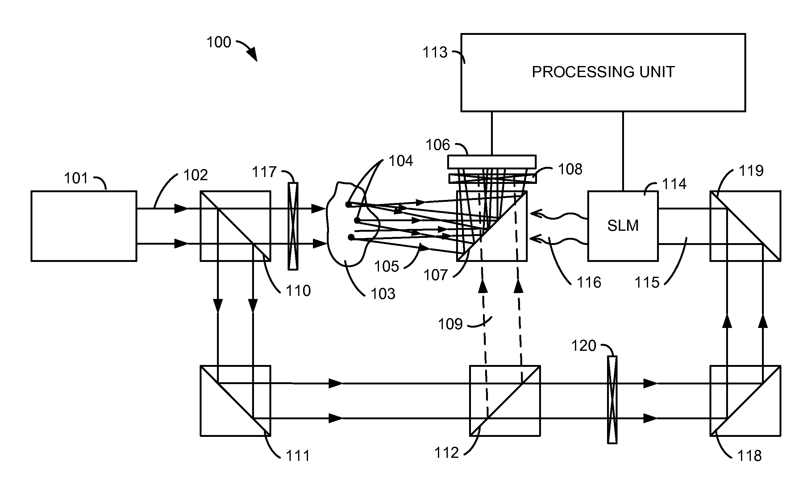
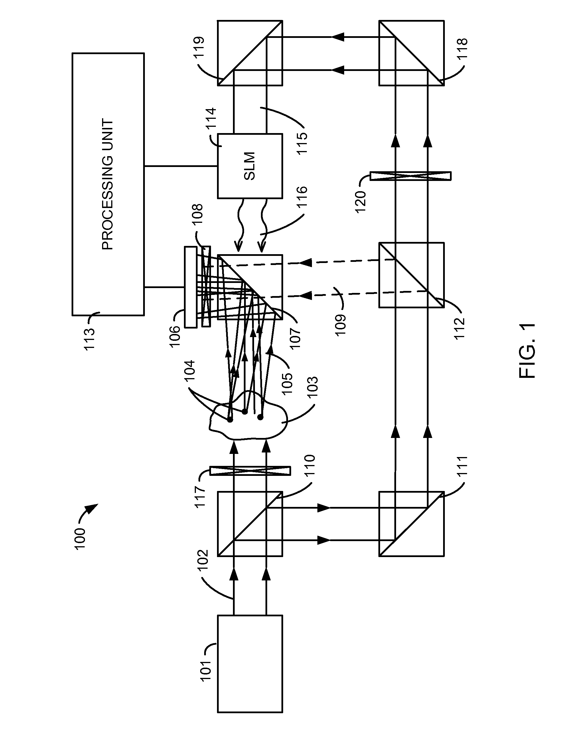
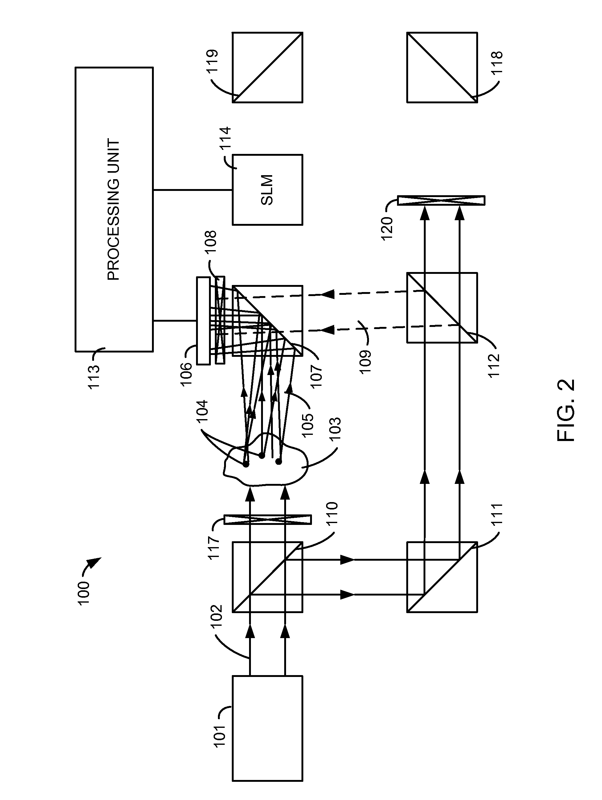
[0017]FIG. 1 illustrates a system 100 in accordance with an embodiment. A laser 101 produces a sample illumination beam 102 that impinges on a turbid or translucent medium 103. Medium 103 may be, for example, a biological medium such as skin tissue, which transmits light readily, but scatters the light passing through it. Certain sites 104 within medium 103 may be tagged or labeled so that they preferentially scatter larger amounts of light than the surrounding tissue. For example, cancer cells within medium 103 may be tagged with metallic nanoparticles using known techniques.

[0018]After the sample illumination beam 102 has passed through medium 103, a sample beam 105 is produced. Sample beam 105 comprises light scattered by medium 103. The scattering appears to be random, but is in fact deterministic, and results from particular features within medium 103. Sample beam 105 is directed to an electronic image sensor 106. For example, sample beam 105 may reflect from a half-reflective ...


PUM


Abstract

An optical system and associated method enable near real time optical phase conjugation. In the method, a translucent medium is illuminated by a sample illumination beam. Light scattered by the medium is directed to an electronic image sensor while a reference beam is also directed to the electronic image sensor. The scattered light and the reference beam form an interference pattern at the electronic image sensor. A digital representation of the interference pattern is recorded using the electronic image sensor, and the characteristics of a conjugate of the sample beam are computed from the numerical representation. A conjugate beam having the computed characteristics is generated using a configurable optical element and directed back to the translucent medium. The generation of the conjugate beam may be accomplished using a spatial light modulator.

Description

[0001]This application claims the benefit of U.S. Provisional Application No. 61 / 242,129, filed on Sep. 14, 2009 and titled “Near Real Time Optical Phase Conjugation”, the disclosure of which is hereby incorporated herein by reference in its entirety.BACKGROUND OF THE INVENTION[0002]Turbid or translucent media present special problems for optical systems. For example, a medium such as biological tissue may transmit light efficiently, but may scatter the light substantially so that it is difficult to see or image through the tissue or to direct light through the tissue to a particular target. The difficulty is not primarily due to the absorption of light by the sample, but to the scattering that interferes with conventional image formation.[0003]While the scattering may appear random, it is actually deterministic. This determinism can be used by advanced optical techniques so that it is possible to compensate for the scattering in the turbid medium. For example, Yaqoob et al. have us...

Claims


Application Information

Patent Timeline
IPC IPC(8): G01B9/021
CPCG01N2201/0675G02B26/06G03H1/2294G03H2001/0072G01N21/4795A61B2018/00642A61B2018/00779A61B18/203A61B2018/00452G03H1/0443
Inventor HENG, XIN
Owner BIO RAD LAB INC
Learn More