Method and device for suppressing hysteresis of resonators through simultaneous resonance

a resonator and simultaneous resonance technology, applied in the field of resonators, can solve the problems of reducing the stability of the resonator, and reducing the signal to noise ratio, so as to increase the signal/noise ratio

Active Publication Date: 2011-09-15
COMMISSARIAT A LENERGIE ATOMIQUE ET AUX ENERGIES ALTERNATIVES
View PDF3 Cites 12 Cited by
  • Summary
  • Abstract
  • Description
  • Claims
  • Application Information

AI Technical Summary

Benefits of technology

[0039]The present invention therefore proposes a device and a method for at least partial cancellation of hysteresis through the implementation of simultaneous resonances in order to negate the influence of the terms of order greater than 5 and to stabilise the cancellation of the nonlinearities. It is then possible to actuate the resonator at very high amplitudes in a linear fashion, and to take full advantage of the improvement in its performance.
[0045]The use, for actuating the deformable element, of at least 2 simultaneous resonances in conformity with the invention makes it possible to operate in a linear regime in an operating range which would be nonlinear without this simultaneous resonance. The operation of the deformable element in a range thus made linear makes it possible to use deformation amplitudes greater than the state of the art and thus to increase the signal / noise ratio.

Problems solved by technology

In other words, in this nonlinear regime, the resonator is no longer stable.
The resonator then becomes difficult to control.
Consequently, not only is the system not stable in open loop, but furthermore the signal to noise ratio is degraded.
This cancellation of the nonlinearities is tricky, however, because it is necessary to cancel rather accurately the terms of order 3.
Moreover, it leads most of the time to the use of very high and unusable voltages.
Thus the influence of terms higher than 3 quickly becomes very large at the usual dimensions of NEMSs, leading to the emergence of highly unstable mixed behaviour, first hardening, then softening.
The problem that presents itself is therefore that of finding a new method and a new device, of the resonator type, that makes it possible to effect a suppression of the hysteresis effect (like that illustrated above in FIG. 2), in a stable manner, while still allowing the attainment of vibration amplitudes high enough to allow an effective reduction of the signal-to-noise ratio of the resonator.

Method used


Image

  • Method and device for suppressing hysteresis of resonators through simultaneous resonance
  • Method and device for suppressing hysteresis of resonators through simultaneous resonance
  • Method and device for suppressing hysteresis of resonators through simultaneous resonance

Examples


Embodiment Construction

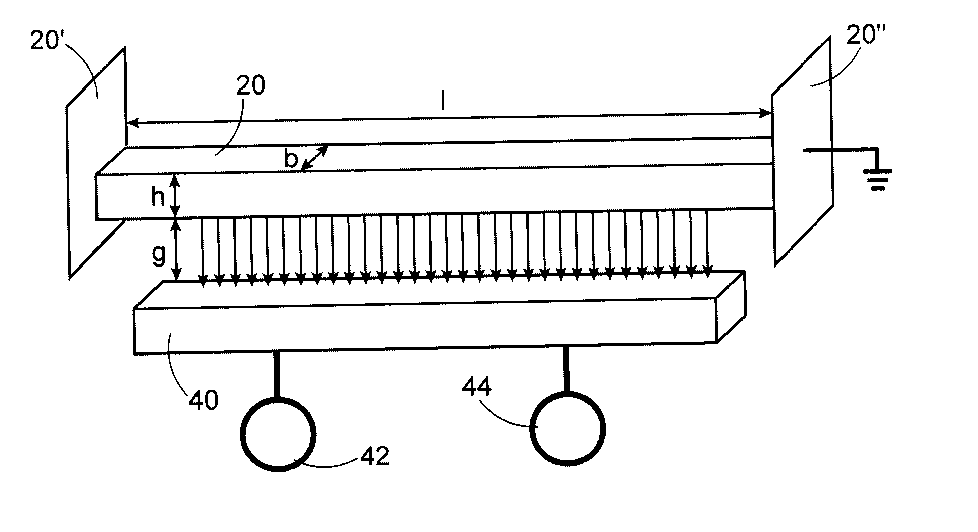
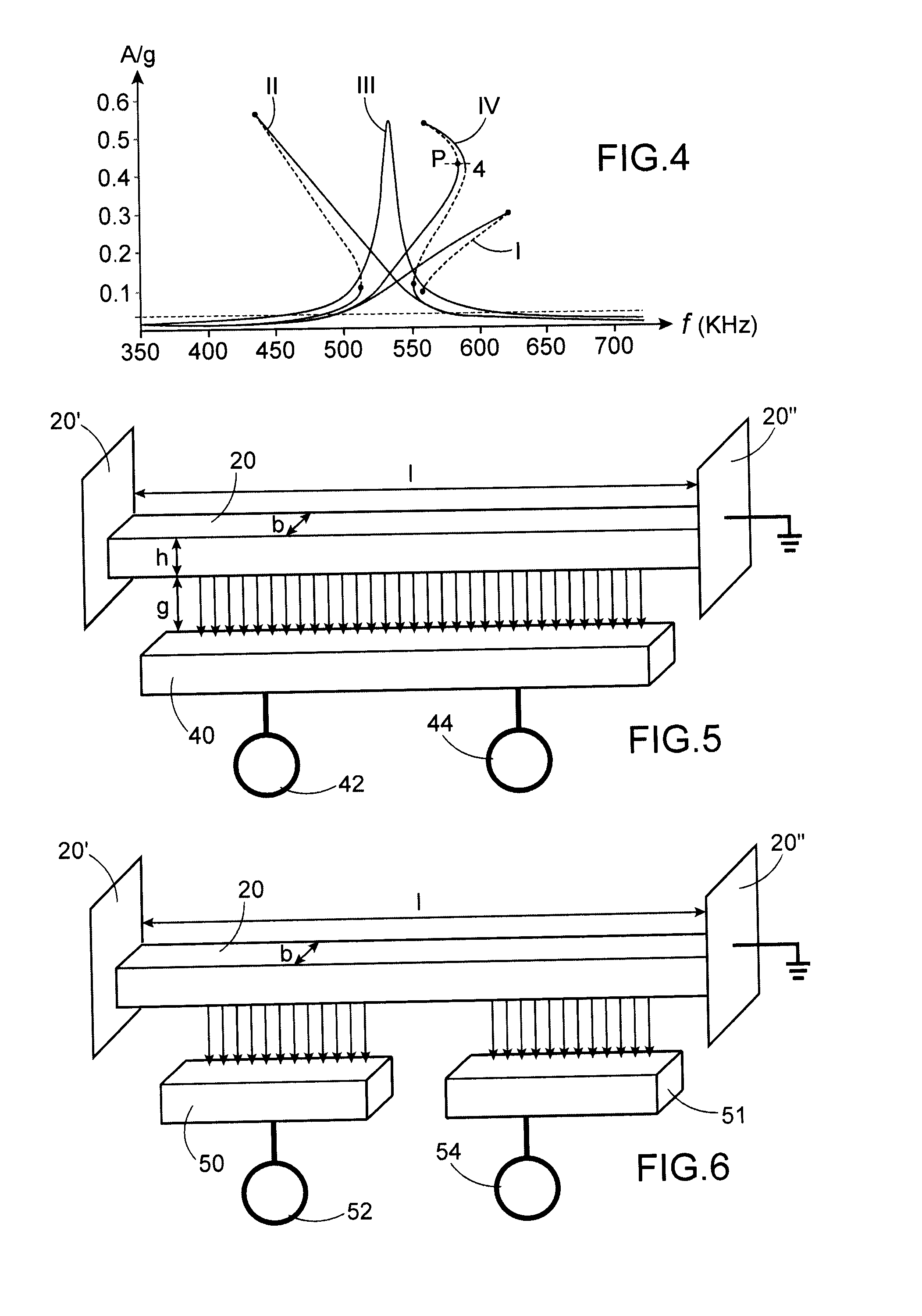
[0051]According to a first example of the invention, a nonlinear resonator is implemented, for example an embedded beam 20, to which are simultaneously applied a super- or subharmonic resonance and a primary resonance. Let us specify that a beam may have a square or rectangular cross section (as in the figures), or any cross-section in variation, particularly circular, as for a nanowire 201 (as in FIG. 13) or a nanotube.

[0052]Let there be a non-linear resonator of order n to which is applied a force of amplitude F and of natural frequency

ω=ω0=keffmeff.

The equation of motion of this resonator is:

meff{umlaut over (x)}+ceff{dot over (x)}+keffx+αnxn=F cos ωt

[0053]If the resonator were purely linear (that is, if αn=0) only a so-called primary resonance would be observed when ω=ω0. The primary resonance is that at which there is resonance if the resonator is purely linear.

[0054]Due to the nonlinear terms, resonances of the resonator are observed in its natural mode at ω0 when ω=ω0 / n (sup...


PUM


Abstract

The invention relates to an electromechanical resonator including at least one deformable element, actuating means for this deformable element for applying to it, simultaneously, at least one first actuating force at a first frequency, and a second actuating force at least one second frequency, the first and second frequencies creating at least two simultaneous resonances at a frequency equal to the frequency of one of the actuating forces.

Description

TECHNICAL FIELD AND PRIOR ART[0001]The invention relates to the field of resonators, particularly of the MEMS or NEMS type.[0002]The applications in question can be resonant sensors, inertial sensors for example, or gas or mass sensors.[0003]Another application is that of creating oscillators for time base application.[0004]In all of these fields, performance (resolution of acceleration, concentration, mass or stability of the generated frequency) is proportional to the signal-to-noise ratio which can be expressed, in a mechanical displacement of the resonator for example, bySNR=P0SXwhere SX is the noise spectral density and P0 the carrier power, namelyP0=12A2,where A is the vibration amplitude of the mechanical resonator.[0005]To improve the performance of the resonator, the largest possible resonator drive amplitude A is sought.[0006]The person skilled in the art always limits this amplitude to a value lower than the so-called critical amplitude, called Ac, beyond which the vibrat...

Claims


Application Information

Patent Timeline
Patent Type & Authority Applications(United States)
IPC IPC(8): H02N1/00G01C19/56
CPCG01C19/56H03H9/02244H03H9/02259H03H2009/02496H03H9/2457H03H9/2463H03H2009/02488H03H9/2436
Inventor HENTZ, SEBASTIENKACEM, NAJIB
Owner COMMISSARIAT A LENERGIE ATOMIQUE ET AUX ENERGIES ALTERNATIVES
Why Eureka
Try Eureka