Pan section

a technology of pan section and slitting machine, which is applied in the direction of transportation and packaging, earthwork drilling and mining, cutting machines, etc., can solve the problems of increasing wear in particular at the intermediate bottom and at the conveyor bottom of the top run, and also at the bottom elements of the bottom

Active Publication Date: 2011-09-15
CATERPILLAR INC
View PDF20 Cites 3 Cited by
  • Summary
  • Abstract
  • Description
  • Claims
  • Application Information

AI Technical Summary

Benefits of technology

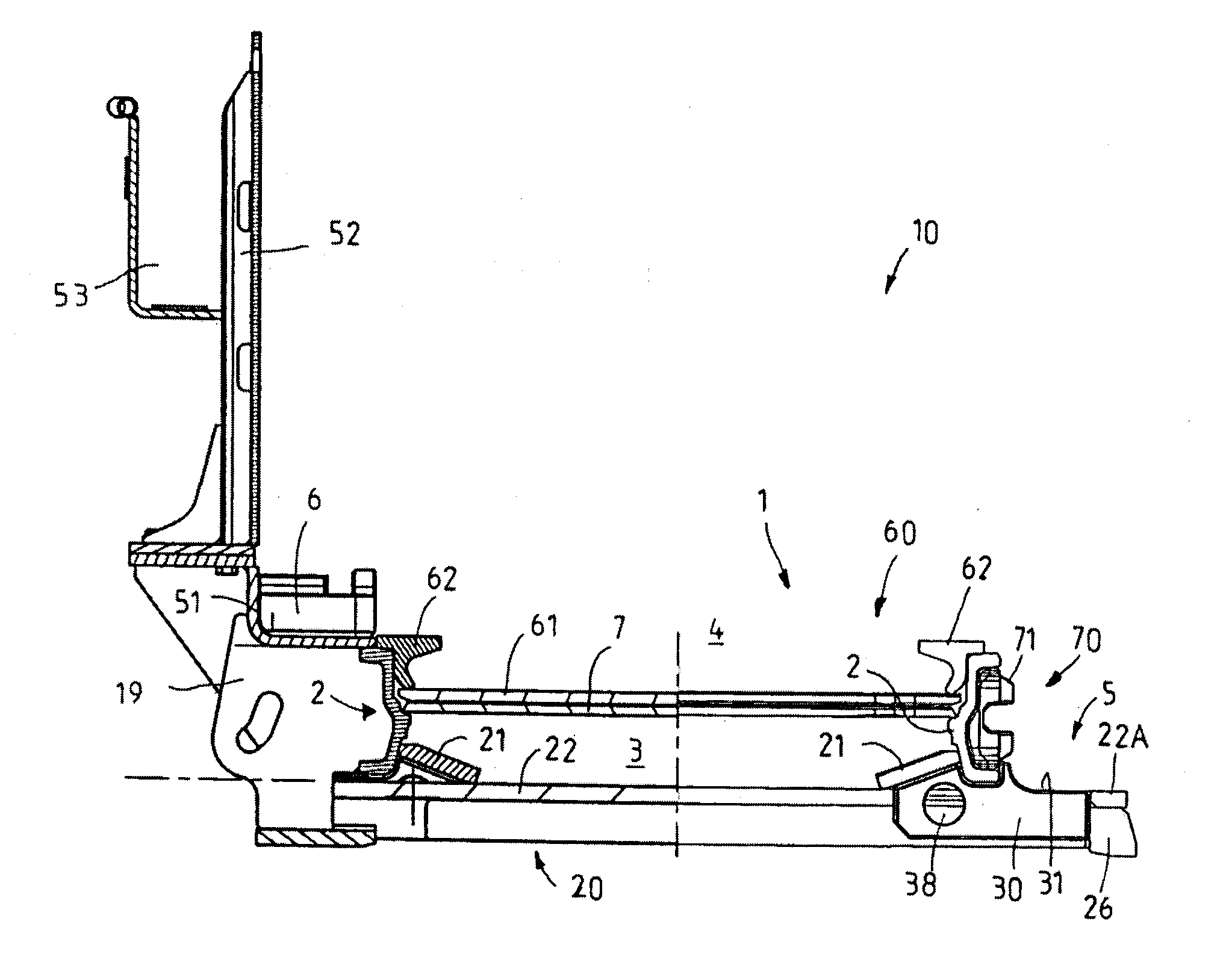
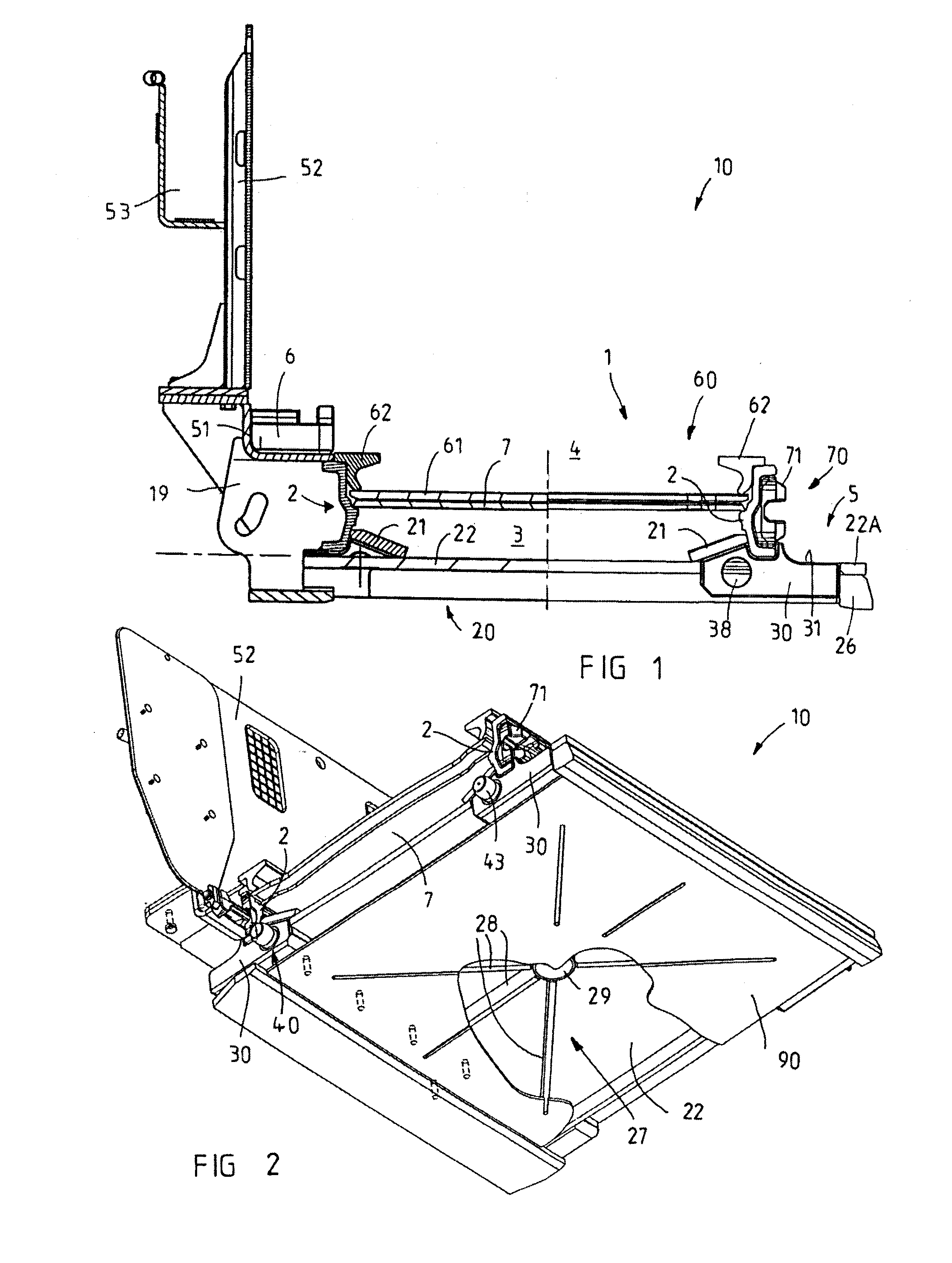
[0007]This object and others is achieved in a pan section of the type in question in that a substructure is provided which is connected to the bottom leg of the rolled profiles, connects both bottom legs to one another at a distance from the intermediate bottom and has mounting pieces positioned at the ends below the bottom legs for transverse-force transmission means. Since shearer loaders whose dead weight can exceed 120 t are used in shearer loader operations for working seam thicknesses greater than, for example, 5 m, the individual pan sections are subjected to considerable forces in operational use, and these forces may lead to increased wear in particular at the intermediate bottom and at the conveyor bottom of the top run, but also at bottom elements of the bottom run, on account of relative movements of adjacent pan sections. Due to the arrangement according to the invention of transverse-force transmission means in a substructure below the bottom legs, the forces occurring in operational use transversely to the conveying direction can be transmitted at a distance from the conveyor base and intermediate base, and, due to the positioning of these means below the rolled profiles in a substructure, there are also no restrictions for the dimensioning of the transverse-force transmission means. At the same time, the substructure provides for additional stiffening of the two rolled profiles relative to one another, such that the central components of each pan section, namely the side cheeks consisting of rolled profiles, can also maintain a larger distance apart than was hitherto normally the case, as a result of which, with wider and possibly also deeper drivers, the conveying output of a conveyor formed with the pan sections according to the invention can be increased in turn.
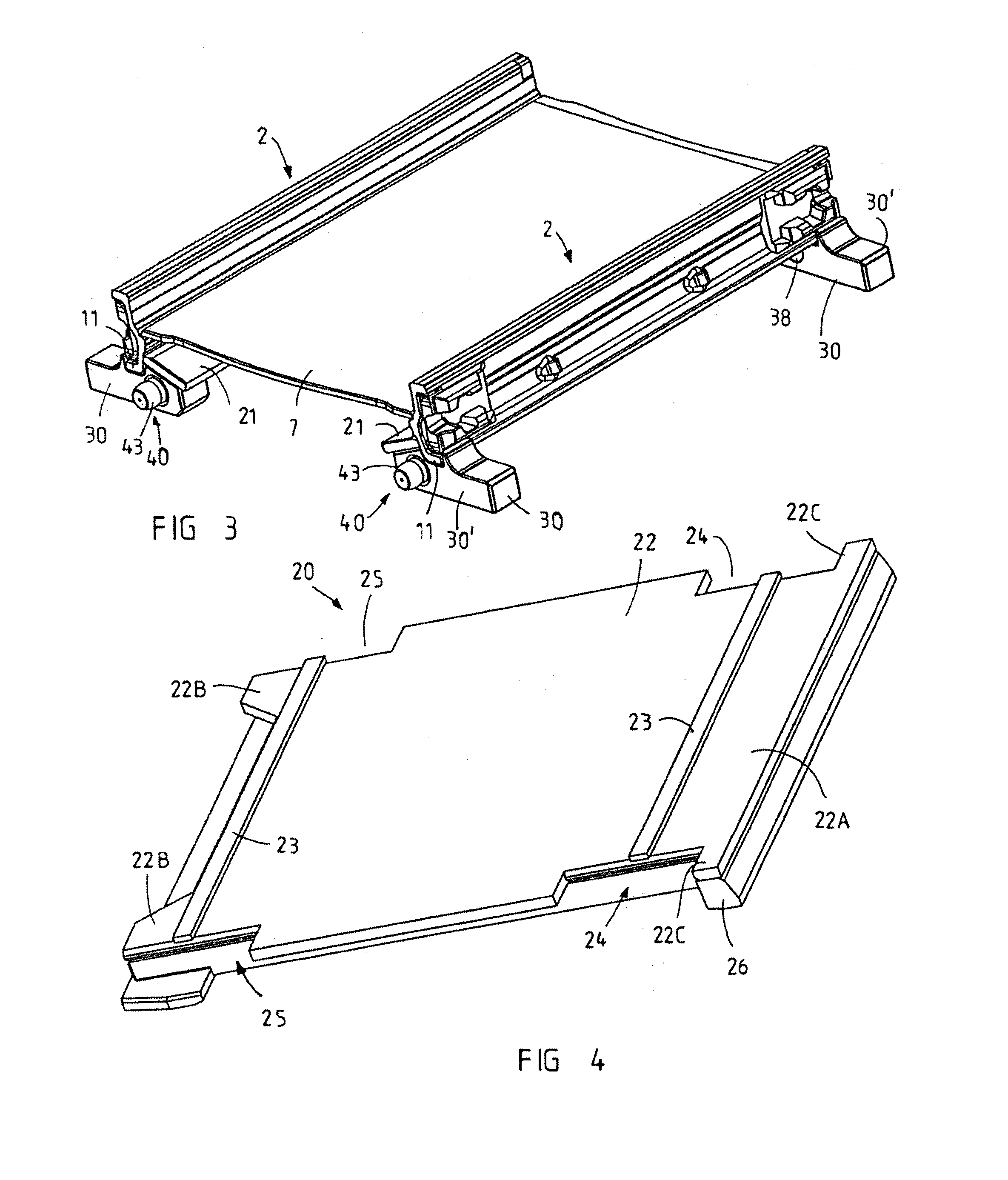
[0009]In order to simplify manufacture, the pegs may consist in particular of pins which have a pin shank, which can be fixedly welded in an aperture or in the aperture in the mounting piece, and a pin head projecting at the end face beyond the mounting pieces in the assembled state. In this configuration, all the mounting pieces can therefore consist of an identically designed basic element having an aperture, wherein some of the mounting pieces are provided with a welded-in pin as peg in order to provide with the same basic part a male part and a female part for the transverse-force transmission means. Since adjacent pan sections in operational use must have a certain angular mobility relative to one another, the pin head, in this configuration, can advantageously be provided with a crowned lateral surface and / or the pin shank merges via a circumferential constriction into the pin head. The crowned lateral surface allows sufficient angular mobility and ensures low pressure forces in the contact zones between aperture and pin head. The constriction provides for the requisite clearance space if adjacent pan sections bear against one another with minimum spacing and are at the same time disposed at an angle to one another. The circumferential constriction at the same time provides for sufficient requisite motional play for the angling both vertically and horizontally, i.e. in the horizontal direction. The mounting pieces for use with pegs can advantageously consist of narrow strips or blocks having an aperture open to the rear side of the mounting pieces, as a result of which the pegs can be fastened or are fastened in the apertures via a welded joint applied from the rear side of the mounting pieces. The female part and the male part of the transverse-force transmission means therefore differ from one another only in the sense that a pin is either inserted as peg in the aperture or is not inserted.
[0011]In order to minimize the plate thickness of the bottom plates, it is especially advantageous if stiffening ribs are integrally formed or are preferably welded under the bottom plate. In this case, the stiffening ribs may be arranged to run transversely and longitudinally and may also be arranged crosswise in order to achieve, with the lowest possible weight of the material of bottom plate and reinforcing ribs, an optimum bending resistance of the substructure extending substantially over the entire depth of the pan section.
[0013]The intermediate leg section of the rolled profiles may in particular have a top intermediate leg section above the offset and a bottom intermediate leg section, shifted inwards relative to said top intermediate leg section, below the offset, wherein the bottom intermediate leg section of the rolled profile, below the step, can form with its inner side at least partly the side walls of the bottom run and / or the top intermediate leg section, above the step and offset, defines with its inner side a receptacle for an interchangeable trough as top run. The use of an interchangeable trough as top run has the advantage that the interchangeable trough, which is generally subjected to the greatest loading and becomes worn quickest, can be exchanged and at the same time the remaining pan section can be used again. As in the prior art of the type in question, the interchangeable trough can be fastened via a welded joint or else via other connecting means.

Problems solved by technology

Since shearer loaders whose dead weight can exceed 120 t are used in shearer loader operations for working seam thicknesses greater than, for example, 5 m, the individual pan sections are subjected to considerable forces in operational use, and these forces may lead to increased wear in particular at the intermediate bottom and at the conveyor bottom of the top run, but also at bottom elements of the bottom run, on account of relative movements of adjacent pan sections.

Method used


Image

  • Pan section
  • Pan section
  • Pan section

Examples


Embodiment Construction

[0026]Referring now to the drawings wherein the showings are for the purpose of illustrating preferred and alternative embodiments of the invention only and not for the purpose of limiting same, designated overall by reference numeral 10 in FIGS. 1 and 2 is a pan section according to the invention for a combined conveying and winning apparatus for underground mining, in particular for the mining of coal. The pan section 10 has a welded frame structure 1 which defines a bottom run 3 and a top run 4 of a conveying apparatus by means of two side cheeks consisting of rolled profiles 2. A conveyor can be formed using a multiplicity of identically constructed pan sections connected to one another via pan-section connecting means 70, and driver elements (not shown), such as in particular scrapers of a scraper chain (likewise not shown), circulate in the bottom run 3 and top run 4 of said conveyor in order to transport coal and other materials away from the face. The top run 4 of the pan se...


PUM


Abstract

A pan section for combined conveying and winning apparatuses having a bottom run and a top run for guiding driver elements of a conveyor chain, as well as a welded frame structure which has two side cheeks which consist of one-piece rolled profiles. The rolled profiles have a constant profile shape with a bottom leg and a top leg, which are angled outwards in the assembled state, and an intermediate leg being provided with an offset for supporting and welding at least one intermediate plate. The pan section further includes a substructure connected to the bottom leg of the rolled profiles to connect both bottom legs to one another at a distance from the intermediate bottom. The substructure also has mounting pieces positioned at the ends below the bottom legs for transverse-force transmission means.

Description

[0001]The invention relates to a pan section for combined conveying and winning apparatuses in particular for underground mining, comprising a bottom run and a top run for guiding the driver elements of a conveyor chain, comprising a welded frame structure which has two side cheeks which consist of one-piece rolled profiles arranged in mirror image and having a constant profile shape from one end to the other end, said profile shape comprising a bottom leg and a top leg, which are angled outwards in the assembled state, and a rising intermediate leg which connects said bottom leg and top leg and which is provided with an offset, on which at least one step for supporting and welding at least one intermediate plate stiffening the rolled profiles in the frame structure is formed on the inside, and comprising mounting pockets for detachable pan-section connecting means which are welded on the outside to the rolled profile between top leg and bottom leg close to both ends.BACKGROUND OF T...

Claims


Application Information

Patent Timeline
Patent Type & Authority Applications(United States)
IPC IPC(8): E21C35/20B65G19/28E21F13/06
CPCB65G19/28E21F13/066B65G19/287
Inventor FISCHER, FRANKSCHMIDT, SIEGFRIEDBAIER, EUGENWIRTZ, JORGTILLESSEN, UWE
Owner CATERPILLAR INC
Why Eureka
Try Eureka