
Optical barrier device

a technology of optical barrier and lens, which is applied in the field of optical barrier devices, can solve the problems of affecting the effect of photography available through the camera, and affecting the effectiveness of photography through the camera

Inactive Publication Date: 2011-09-08
STUTES RICHARD DALE
View PDF15 Cites 5 Cited by
  • Summary
  • Abstract
  • Description
  • Claims
  • Application Information

AI Technical Summary

Problems solved by technology

One drawback to using covering on an intraoral cameral is that the camera produces a significant amount of heat and moisture.
Therefore use of a plastic covering can fog the camera lens and therefore inhibit the view available from the camera while the plastic covering is in place.
Consequently, it would be advantageous to have a plastic covering that can effectively provide a infection control barrier but yet does not cause fogging of the camera lens and the barrier making the photography available through the camera less effective.

Method used


Image

  • Optical barrier device
  • Optical barrier device

Examples


Embodiment Construction

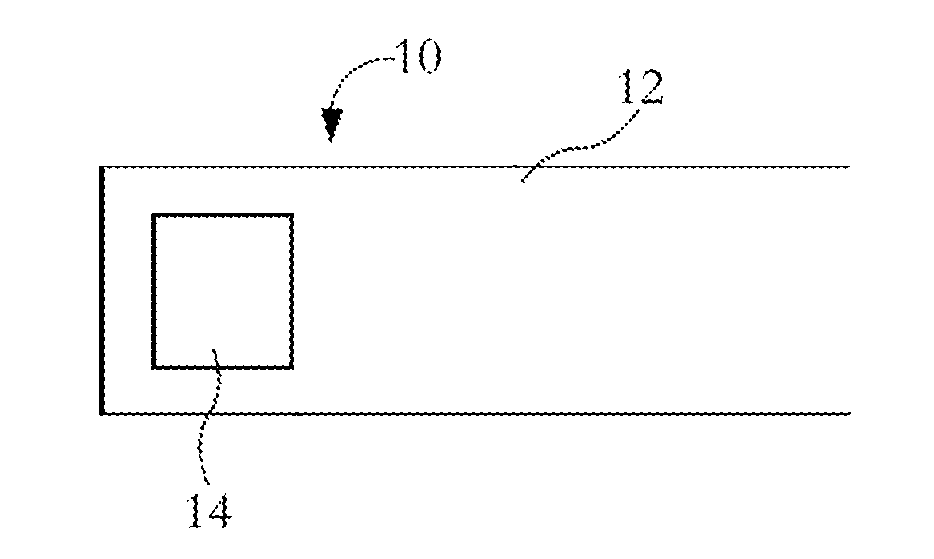
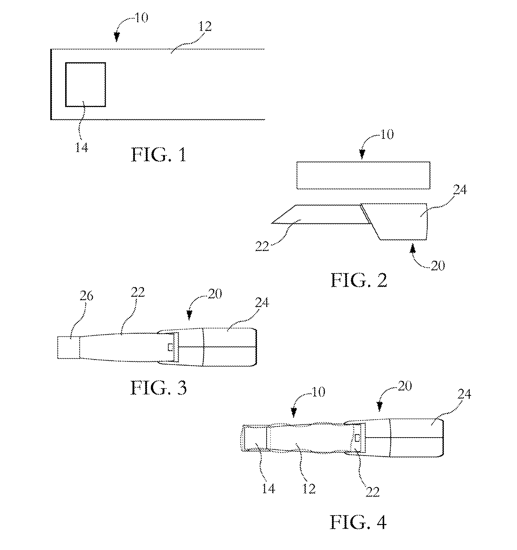
[0011]The present invention provides a means to prevent and eliminate contamination of intraoral cameras during use in a dental office. Infection control is a primary concern of every dental office and with the wide use of intraoral cameras, the present invention provides a solution consisting of a protective barrier that covers the intraoral camera and therefore helps to maintain the camera in a sterilized and infection free state. The optical protective barrier according to present invention essentially is a plastic covering with inclusion of a hard plastic clear lens anchored within the plastic covering. The hard plastic clear lens is positioned over the lens of the intraoral camera and therefore helps to eliminate the fogging and other drawbacks related to the use of a conventional plastic covering over an intraoral camera.

[0012]An exemplary Optical Barrier Device 10 is depicted in FIG. 1. The Barrier Device 10 includes a flexible plastic body that has a hard plastic clear windo...


PUM


Abstract

The present invention relates to a protective barrier device for covering an intraoral camera comprising: a flexible plastic body, said body having an opening for inserting the intraoral camera; and a hard clear plastic window at the distal end of the plastic body. The flexible plastic body is of sufficient length to cover the entire length of an appendage of the intraoral camera. The window aligns with a camera lens of the intraoral camera when the plastic body is placed over the appendage and may be constructed of a fog-resistant plastic.

Description

BACKGROUND OF THE INVENTION[0001]1. Field of Invention[0002]The present invention relates to an optical barrier device used to protect a patient from the transfer of germs or bacteria that may occur through the use of dental instruments.[0003]2. Description of Related Art[0004]It is imperative for dental instruments to remain free of bacteria and germs that can cause cross-contamination between and among patients. Dental instruments may be used on several patients over a given period of time. Many dental instruments require sterilization immediately after use while others may be disposed of after a single use. In addition to sterilization and disposal, another technique to maintain bacteria free instruments includes the use of covering or draping of instruments during the use. U.S. Pat. No. 4,723,912 discloses a draping apparatus for covering dental and medical equipment and appendages extending therefrom such as water hoses, electrical cords and the like. U.S. Pat No. 5,217,370 dis...

Claims


Application Information

Patent Timeline
Patent Type & Authority Applications(United States)
IPC IPC(8): G02B27/00
CPCG02B27/00A61B1/00142
Inventor STUTES, RICHARD DALE
Owner STUTES RICHARD DALE
Learn More