Artificial lift system and method for well

a technology of lift system and lift rod, which is applied in the direction of wellbore/well accessories, fluid removal, sealing/packing, etc., can solve the problems of sucker rod guide wear, and difficulty in locating a sucker rod pump therein

Active Publication Date: 2011-09-08
HARBISON FISCHER
View PDF15 Cites 24 Cited by
  • Summary
  • Abstract
  • Description
  • Claims
  • Application Information

AI Technical Summary

Benefits of technology

[0008]An artificial lift system is for use in a well. The well extends from the surface of the earth through a producing formation. The well having an annulus. The system comprises a downhole fluid lifting mechanism located in the well. The fluid lifting mechanism has a fluid operating level wherein fluid located at the fluid operating level is operated on by the fluid lifting mechanism to be lifted to the surface. The fluid lifting mechanism communicat

Problems solved by technology

In many horizontal wells, it is difficult to locate a sucker rod pump therein because the pump cannot traverse the curved portion of the well.
In addition, pumps that can be installed in the horizontal sect

Method used


Image

  • Artificial lift system and method for well
  • Artificial lift system and method for well
  • Artificial lift system and method for well

Examples


Embodiment Construction

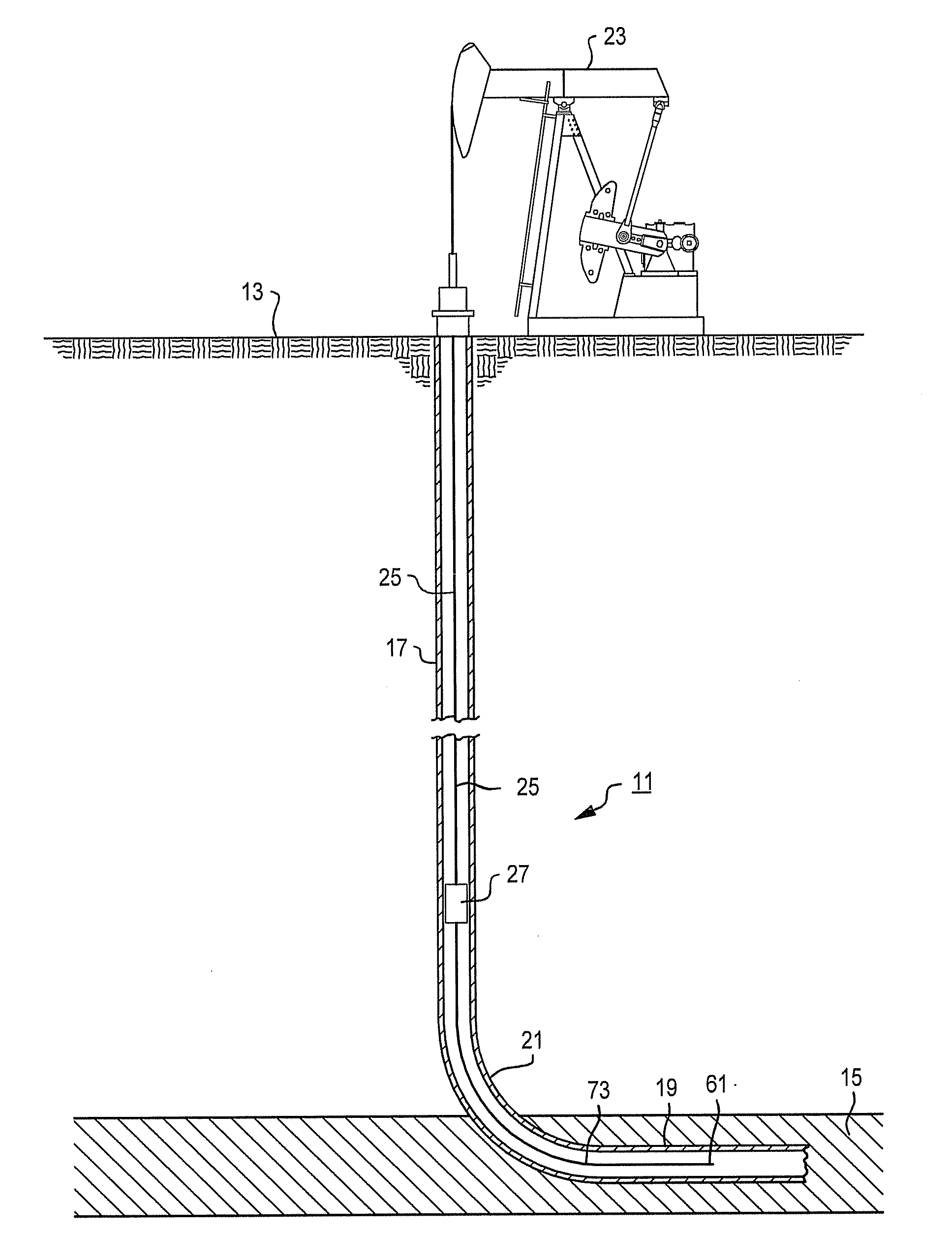
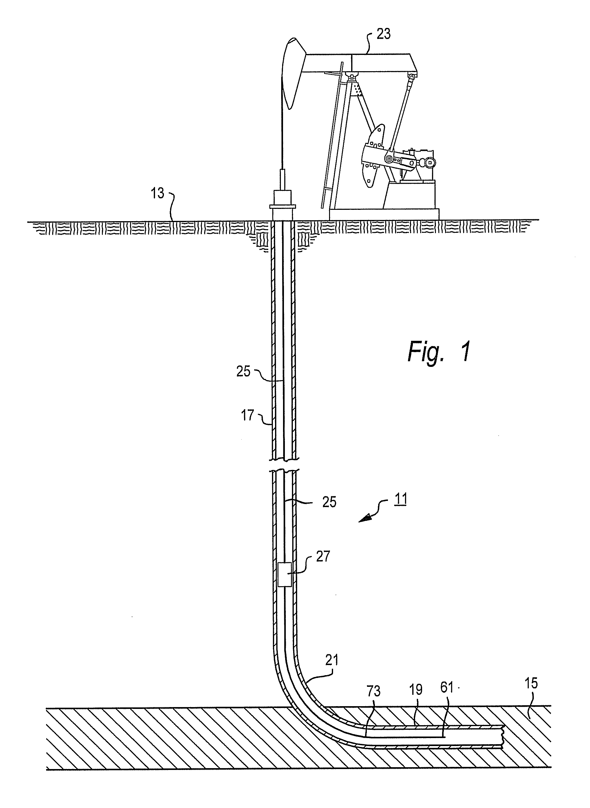
[0032]The system and method described herein allows the use of artificial lift in a horizontal well without the need for locating the lifting components in the horizontal portion of the well. Thus, the lifting components need not traverse the curved portion of the well. This allows a more effective artificial lift mechanism to be utilized in the well. The system and method also allow the use of artificial lift in a vertical well. There may be other features and advantages which will become known in the future.

[0033]In the description that follows, terms such as “above”, “upper”, and “lower” are used, with reference to the distance from the surface inside of the well. For example, in a horizontal well, a “lower” end of a component is further from the surface, through the well, than the “upper” end. Also, in the drawings, like reference numbers designate like components (for example, casing 31).

[0034]FIG. 1 shows a typical horizontal well 11 which may produce oil, water, natural gas o...


PUM


Abstract

An artificial lift system provides a lifting mechanism located in a well. The lifting mechanism communicates with a remote intake that is located below in the well. A compressed gas source provides compressed gas to the well annulus at a pressure that is sufficient to move the well fluid from the remote intake up to the lifting mechanism. The well has an annulus and tubing. The well has isolation elements that isolate the producing formation from compressed gas in the annulus. Various sources of compressed gas can be used such as a compressor, an accumulator or a gas sales line. A controller is provided to control the intermittent application and removal of compressed gas in the annulus and also to control the operation of the lifting mechanism. The well could be a horizontal well or a vertical well. The well could be a cased hole or an open hole well.

Description

[0001]This application claims the benefit of U.S. provisional patent application Ser. No. 61 / 310,454, filed Mar. 4, 2010.FIELD OF THE INVENTION[0002]The present invention relates to artificial lifting systems and methods for use in wells such as horizontal wells.BACKGROUND OF THE INVENTION[0003]Traditional oil and gas wells are drilled with boreholes extending from the surface vertically down to some depth to a pay zone. The pay zone contains the formation with the hydrocarbons of interest.[0004]Some geological formations become more productive if the wells extend horizontally into and stay within the formations. Horizontal wells are initially drilled as vertical wells. At some depth, the borehole turns from vertical to horizontal. There is a radius of curvature of the borehole as it changes orientation from vertical to horizontal.[0005]Many wells, after producing for some time, require artificial lift. For example, oil wells may require the oil to be pumped to the surface; gas well...

Claims


Application Information

Patent Timeline
IPC IPC(8): E21B43/00
CPCE21B43/00E21B43/122
Inventor ROGERS, BRADLEY CRAIG
Owner HARBISON FISCHER
Why Eureka
Try Eureka