
Laser Focused Ablation Apparatus and Method of Use in Revision Arthroplasty

a laser focused ablation and arthroplasty technology, applied in the field of laser focused ablation system, can solve the problems of reduced femur strength, significant residual damage to the cortical bone of the femur, etc., to accurate control of the ablation volume, and reduce the risk of significant damage to the bone.

Inactive Publication Date: 2011-09-01
EZENWA BERSTREETCAR +1
View PDF15 Cites 1 Cited by
  • Summary
  • Abstract
  • Description
  • Claims
  • Application Information

AI Technical Summary

Benefits of technology

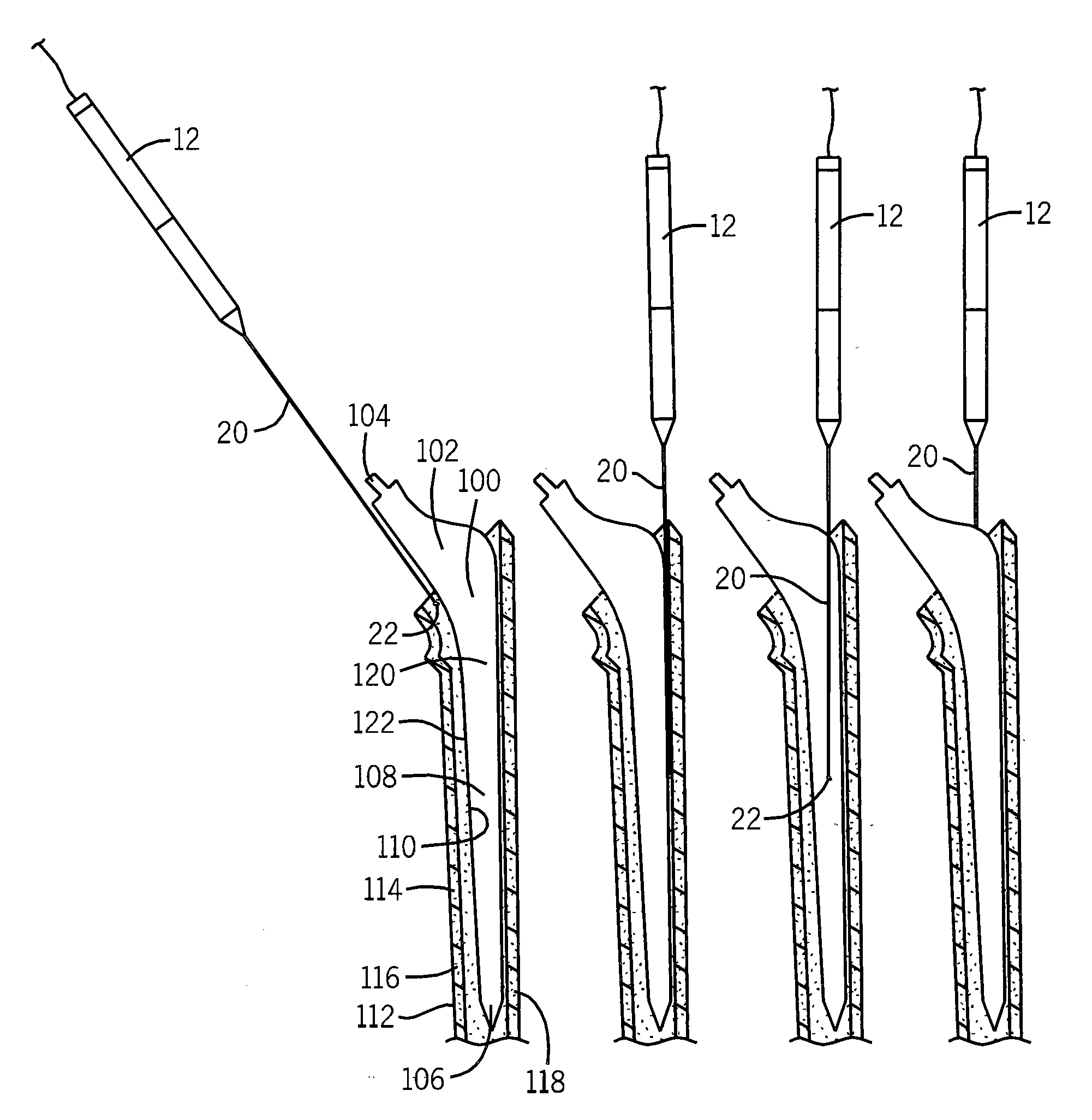
[0009]The present invention provides a laser system that can rapidly ablate the cement mantle surrounding a failed hip prosthesis stem, during a revision arthroplasty, with minimized mechanical trauma to the bone. Use of a laser focused ablation device provides the surgeon with the ability to ablate bone cement working from the entrance aperature of the prosthesis stem along the depth of the stem without bone removal and accurate control of the ablation volume, limiting damage to both the surrounding cancellous and cortical bone tissue.
[0011]Thus it is one object of the invention to provide a means for removing a failed hip stem from a femur while minimizing collateral damage to the surrounding bone tissue, allowing the replacement prosthesis to fixate more securely.
[0013]Thus it is another object of the present invention to provide a focused ablation penetration pathway the orientation of which is accurately controlled by surgeon.

Problems solved by technology

Each of the routine surgical methods employed to remove a failed hip stem during a revision arthroplasty include significant risks of significant damage to the bone.
The chisel method may also result in residual damage to the cortical bone of the femur.
Any such reduction in femur strength may jeopardize a patient's early return to full load bearing following artificial hip revision surgery.
Furthermore, collateral damage to the spongy bone tissue, i.e. cancellous bone tissue, located internal to the cortical bone tissue of the femur, may occur.
As the spongy bone tissue is critical in bearing stress exerted on the femur, any damage will impede the bone's ability to return to full remodeling functions, and thereby prolong full patient recovery.

Method used


Image

  • Laser Focused Ablation Apparatus and Method of Use in Revision Arthroplasty
  • Laser Focused Ablation Apparatus and Method of Use in Revision Arthroplasty
  • Laser Focused Ablation Apparatus and Method of Use in Revision Arthroplasty

Examples


Embodiment Construction

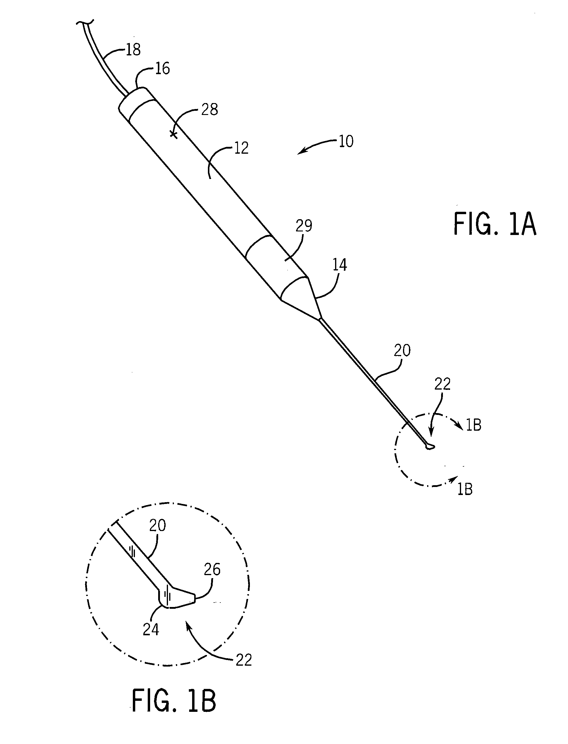
[0025]Referring initially to FIG. 1A, the present invention provides a laser focused ablation device 10. The device 10 is configured of a handpiece 12 having a first end 16 and a second end 14. The first end 16 receives a laser light along a connection means 18. The laser light is then transmitted through the handpiece 12 to the opposing side at second end 14. The elongated main conduit 20 is operably connected to the second end 14 of the handpiece, and designed to transmit the laser light therein. The elongated main conduit 20 ends at a tip 22. The tip 22 includes both a curvature 24 and a tip 26, as illustrated in greater detail in FIG. 1B.

[0026]Returning to FIG. 1A, the handpiece 12 is designed to fit comfortably within the hand of a surgeon. In one embodiment the handpiece 12 is cylindrical, and has a longitudinal length of greater than 75 millimeters and less than 250 millimeters, and a diameter of greater than 3 millimeters and less than 25 millimeters. The second end 14 may i...


PUM


Abstract

The present invention provides and a laser focused ablation apparatus and method of use configured to ablate a cement mantle surrounding a stem of a hip prosthesis, for use during a revision arthroplasty. The apparatus comprises a laser generation system generating a laser light and a handpiece to receive the laser light. The handpiece includes an elongated main conduit terminating at a laser emission tip, the laser emission tip providing a tip and a curvature disposed between the tip and the elongated main conduit such that the laser light exits the tip at a direction oblique to a longitudinal axis of the elongated main conduit.

Description

CROSS REFERENCE TO RELATED APPLICATION[0001]This application claims the benefit of U.S. provisional application 61 / 309,162 filed Mar. 1, 2010 and hereby incorporated by reference.STATEMENT REGARDING FEDERALLY SPONSORED RESEARCH OR DEVELOPMENT[0002]1. Field of the Invention[0003]This invention relates generally to a laser focused ablation system and methods of use, particularly for use in the ablation of orthopedic cement during revision arthroplasty.[0004]2. Brief Description of the Prior Art[0005]A significant percentage of all hip arthroplasties constitute revisions of previously placed hip prostheses. The revision procedure typically includes the removal of a previously placed hip prosthesis, which has failed, and replacing it with a new hip prosthesis. On average revision arthroplasty is required 8 to 10 years after a hip prosthesis has been initially placed. As life expectancy continues to rise and patients undergo primary hip replacements at an earlier age, the need for revisi...

Claims


Application Information

Patent Timeline
Patent Type & Authority Applications(United States)
IPC IPC(8): A61B18/20
CPCA61B17/1664A61B18/22A61F2/32A61B2018/2272A61B2018/2288A61B18/24
Inventor EZENWA, BERTRAMLIMONI, ROBERT
Owner EZENWA BERSTREETCAR
Learn More