
Motor starting and switching

a technology of motor starting and switching, applied in the direction of motor/generator/converter stopper, polyphase induction motor starter, dynamo-electric converter control, etc., can solve the problems of severe oscillatory pulsation of torque generated by the motor, the number of additional undesirable phenomena, and the motor protection problem, etc., to achieve repeatable and accurate timing of contact closure and time more accurately

Active Publication Date: 2011-09-01
ROCKWELL AUTOMATION TECH
View PDF16 Cites 19 Cited by
  • Summary
  • Abstract
  • Description
  • Claims
  • Application Information

AI Technical Summary

Benefits of technology

[0007]The present inventors have discovered that it is, however, possible to reduce or eliminate both the torque pulsation and the doubling of inrush current by modifying the way in which starter contactors are switched on. Traditionally, in a 3-phase system, the contacts for each of the three phases are closed at the same time. This simultaneous closure generates a transient current surge in addition to the expected locked rotor current, and an associated transient pulsation in torque. If, on the other hand, in a 3-wire system connected by connecting devices such as contactor poles placed between the supply and the motor terminals, two contacts are closed first when the line voltage between the two phases is at its peak value, and then the third contact is closed a quarter of a cycle later, both the torque pulsation and surge current are reduced or eliminated.
[0009]In due course, an explanation will be presented as to why this simple modification in the contactor switching sequence is effective. It will be referred to as point on wave (POW) switching. Methods of control to achieve this are described, and its application to direct-on-line (DOL) starting of both Y-connected and Delta-connected motors. POW switching may also be applied to minimise the unpleasant and serious transients that accompany the transition from wye (Y) to delta connection in Y-delta starters, and can also reduce the huge surge currents that occur when transformers are energized, and in connecting standby and wind generators to either transformers or to the mains supply.
[0011]In typical embodiments, at least one of the windings is connected by means of electrically controlled single contactor poles. Advantageously, at least one contactor pole is connected by means of a switched DC voltage source to achieve repeatable and accurate timing of contact closure. In this context, controlling the connector pole using DC allows its closure to be timed more accurately than would be the case with an AC-controlled connector pole.
[0031]A consequential 50% reduction in harmful peak torques in mechanical loads and electrical windings.
[0032]A reduction of system-wide surge overcurrents allows circuit breakers to be set at levels to ensure system robustness and thereby improve plant-wide up-time and overall safety. Present industry practice is to set trip currents 50% higher than desired in order to avoid nuisance tripping of circuit breakers by surge overcurrents.
[0037]A significant decrease in plant-wide electrical and mechanical maintenance with consequent reductions in down time and improvement in safety.

Problems solved by technology

However, a number of additional undesirable phenomena occur which are caused by the sudden connection of the supply to the motor.
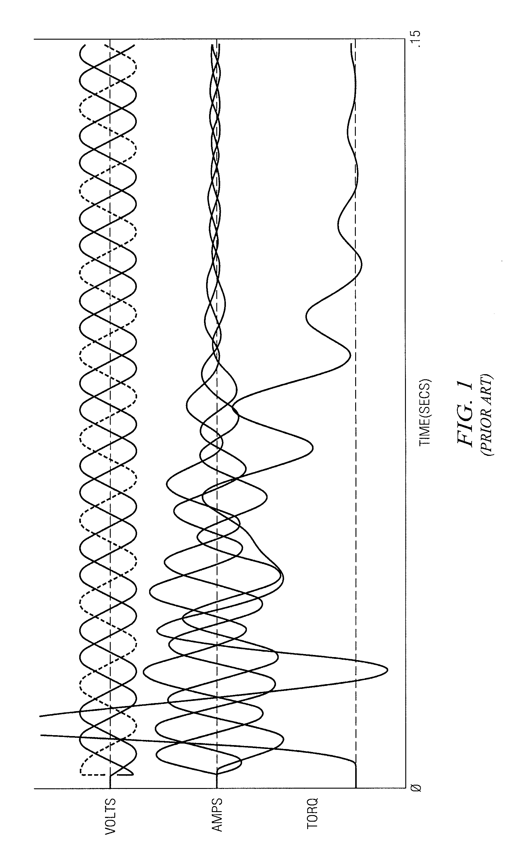
Most obviously, during the first fraction of a second or so following switch-on (increasing to many seconds for large motors), there is a severe oscillatory pulsation in torque generated by the motor.
This variation in torque can be a significant factor in causing breakdown, especially in motors subject to frequent starting.
Less obvious, but just as serious, is the fact that during the transient period of torque pulsation, supply current peaks can be up to twice the expected steady-state locked rotor starting current.
This abnormally high current is known as surge current, and can cause problems for motor protection.

Method used


Image

  • Motor starting and switching
  • Motor starting and switching
  • Motor starting and switching

Examples


Embodiment Construction

[0067]As an introduction to the thinking behind the invention, there will now be presented a brief description of how simultaneous switching of three phases during starting of a motor generates transient surge currents. When an induction motor is at rest, the internally generated back-e.m.f. is zero. If the stator resistance R, is ignored, then when the supply is applied, current flow is determined by the stator inductance. If all three phases are energised together, the current flow is made up of the balanced steady-state 3-phase AC starting current that will flow plus an exponentially decaying DC transient current, present in differing amounts in each phase.

[0068]The amplitude of the DC transient is determined at the moment of connection when all currents are zero, and their rate of change is limited by the motor inductance. It follows that at the moment immediately after connection the currents must still be zero, before they have had time to grow. Hence, immediately after connec...


PUM


Abstract

A method of starting and apparatus for starting a multiphase electrical machine is disclosed. The aim is to reduce oscillatory pulsation in torque generated by the motor and inrush current that occurs shortly after start-up. The starting method comprises the steps of first connecting at least one, but less than all, of a plurality of windings to a respective phase-shifted supply voltage at a controlled point in the supply phase. Then, after a controlled delay following the first connection, connecting the or each remaining winding of the machine a respective phase-shifted supply voltage. The invention has particular application to multiphase (most usually, 3-phase) motors. However, it can also be applied to other electrical machines, such as generators and transformers. The method can be performed at initial start-up or, in the case of application to a motor, at Y-delta switchover.

Description

CROSS REFERENCE TO RELATED APPLICATION[0001]This application is a divisional application of U.S. application Ser. No. 11 / 575,890 filed on Jul. 18, 2007, which claimed the benefit of PCT / GB05 / 003503 filed Sep. 12, 2005, which claimed the benefit of GB0421443.3 filed Sep. 27, 2004.TECHNICAL FIELD OF THE INVENTION[0002]This invention relates to a control system for motor starting and switching, to motors, and to methods for starting and switching motors.BACKGROUND OF THE INVENTION[0003]When an electromagnetic contactor is used to start up an induction motor from rest, during acceleration the motor draws a starting current from the supply that is between six and ten times motor full load current (FLC), depending on the size and construction of the motor. As the motor approaches full speed, the current falls to the full load value, or less if the load on the motor is less than full load.[0004]However, a number of additional undesirable phenomena occur which are caused by the sudden conne...

Claims


Application Information

Patent Timeline
Patent Type & Authority Applications(United States)
IPC IPC(8): H02J3/42H02P1/24
CPCH02P1/24H02P1/029H02P1/26
Inventor UNSWORTH, PETERKINSELLA, JAMES JOSEPH
Owner ROCKWELL AUTOMATION TECH
Learn More