
Knee Rehabilitation exercise device

Active Publication Date: 2011-08-25
BURNS JEBODIAH MOSE
View PDF6 Cites 35 Cited by
  • Summary
  • Abstract
  • Description
  • Claims
  • Application Information

AI Technical Summary

Benefits of technology

[0007]The primary object of the invention is to provide a knee rehabilitation exercise device that allows a person to strengthen leg muscles after knee surgery.
[0008]Another object of the invention is to provide a knee rehabilitation exercise device that helps increase the range of knee joint motion.
[0009]Another object of the invention is to provide a knee rehabilitation exercise device that can be easily used by a person without the need for additional help from a care giver.
[0010]A further object of the invention is to provide a knee rehabilitation exercise device that is light weight and can be adjusted to fit a variety of leg lengths and diameters.
[0011]Yet another object of the invention is to provide a knee rehabilitation exercise device that can be fastened to a user's leg quickly and easily.

Problems solved by technology

With today's rigorous sports activities including football, tennis, basketball and soccer it is unfortunately a common occurrence for active people to injure there knee joint to the point where surgical treatment is necessary to repair the knee and areas around the knee.
However, these patents and other commercially available exercise devices have a deficiency in that none of them allows a person to wear a light weight inexpensive brace which has hooks attached to allow the user to releasably attach an elastic band from the area of the upper leg to the area of the lower leg, and to insert a portable assembly behind the user's knee for the elastic band to stretch over to increase the resistance factor to the muscles surrounding the knee joint.
Furthermore, none of the patents or other prior art shows a leg brace exercise device that allows the user to easily and quickly change the resistance band location from the back of the leg to the front of the leg whereby the user can insert a portable assembly in front of the knee which the elastic band passes over to passively stretch the knee joint to a straight position.

Method used


Image

  • Knee Rehabilitation exercise device
  • Knee Rehabilitation exercise device
  • Knee Rehabilitation exercise device

Examples


Embodiment Construction

[0031]Detailed descriptions of the preferred embodiment are provided herein. It is to be understood, however, that the present invention may be embodied in various forms. Therefore, specific details disclosed herein are not to be interpreted as limiting, but rather as a basis for the claims and as a representative basis for teaching one skilled in the art to employ the present invention in virtually any appropriately detailed system, structure or manner.

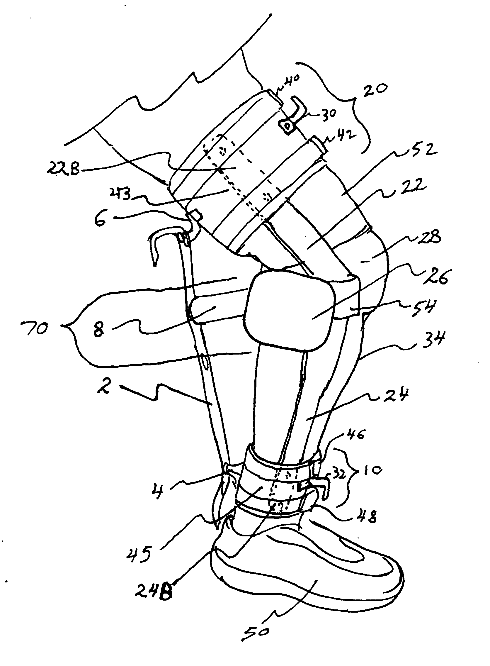
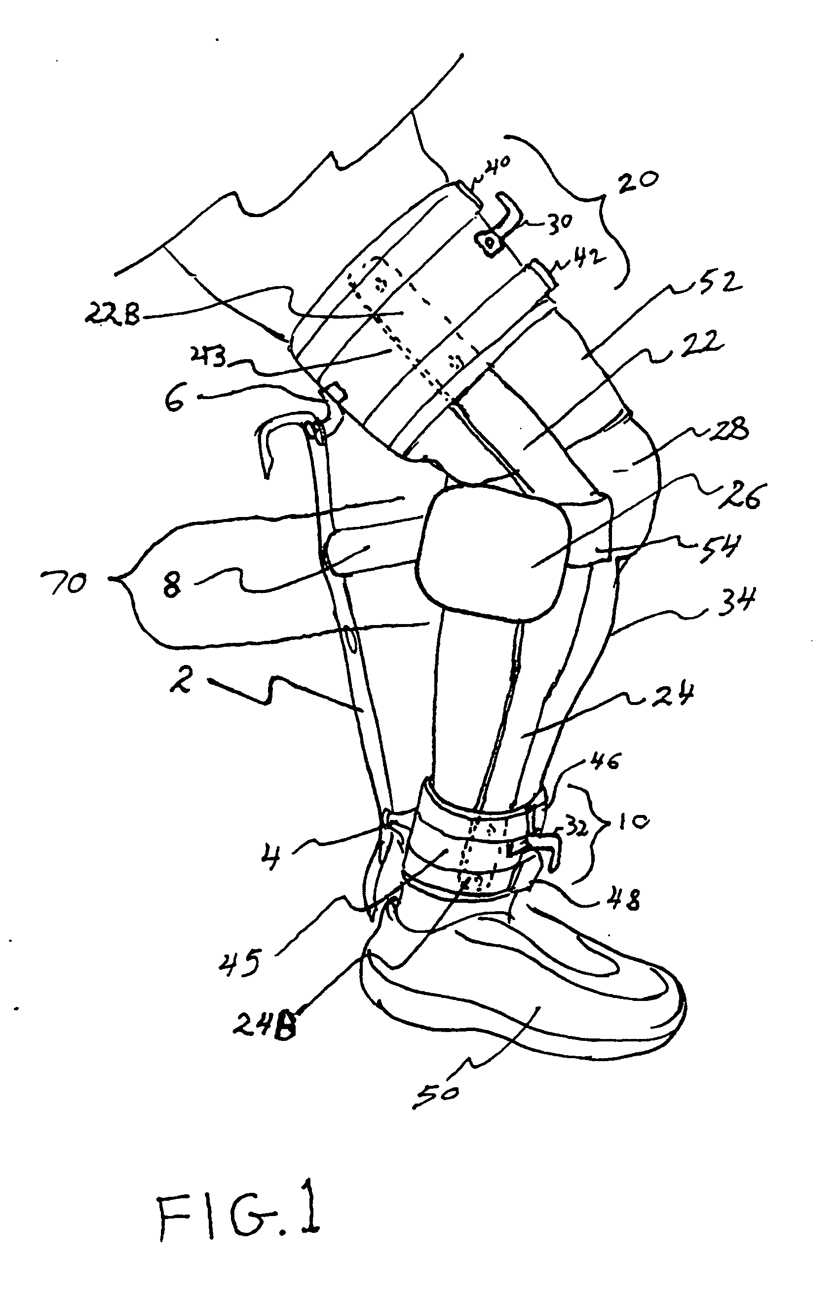
[0032]Referring now to FIG. 1 we see a side view of a person's leg 34 and wearing the leg brace of the present invention. A top flexible leg strap assembly 20 is attached to a pair of rigid leg braces. Each leg brace is comprised of an upper half 22 and a lower half 24. Both left and right leg braces can be seen clearly in FIG. 11 and are shown as left brace 22, 24 and right brace 22A and 24A. The rigid leg brace members are pinned as shown by dotted lines 14, 16 in FIG. 4 to an intermediate plate 12 that connects upper brace member ...


PUM


Abstract

A knee rehabilitation exercise device with a right and left leg brace, a rear knee strap, an upper leg strap assembly, a lower leg strap assembly, a portable rear brace assembly and an elastic resistance band. The left and right leg brace members are each comprised of an upper member and a lower member rotatably pinned together at the area of the knee joint. The left and right leg braces are attached to the upper and lower leg strap assembly. The rear knee strap is attached to the left and right leg braces at the knee joint. When a user places the elastic band onto L hooks mounted on the upper and lower strap assembly and the rear brace assembly is placed between the rear of the user's knee and the elastic band, a resistive stretching is caused when the user straightens his leg which exercises and strengthens the user's leg muscles in the area of the knee joint.

Description

CROSS REFERENCE TO RELATED APPLICATIONS[0001]Not ApplicableSTATEMENT REGARDING FEDERALLY SPONSORED RESEARCH OR DEVELOPMENT Not ApplicableDESCRIPTION OF ATTACHED APPENDIX[0002]Not ApplicableBACKGROUND OF THE INVENTION[0003]This invention relates generally to the field of portable leg exercise devices and more specifically to a knee rehabilitation exercise device.[0004]With today's rigorous sports activities including football, tennis, basketball and soccer it is unfortunately a common occurrence for active people to injure there knee joint to the point where surgical treatment is necessary to repair the knee and areas around the knee.[0005]Because of this, it has been necessary to provide devices to help rehabilitate the knee area after surgery. Some devices are simply leg braces that help take pressure off the knee joint while it is healing. Other devices are machines or apparatus that help strengthen the leg muscles around the knee and associated with proper knee function.[0006]Pat...

Claims


Application Information

Patent Timeline
IPC IPC(8): A63B21/02
CPCA61F5/0123A61F2005/0137A61F2005/0179A63B21/0004A63B21/0421A63B2022/0094A63B21/0552A63B21/0557A63B21/1426A63B21/1449A63B23/0494A63B21/0442A63B21/4013A63B21/4025A63B23/0405A63B21/4039A63B21/0407A63B23/03508
Inventor BURNS, JEBODIAH MOSE
Owner BURNS JEBODIAH MOSE
Learn More