Surface light source device and display device
a light source device and surface technology, applied in the direction of lighting and heating apparatus, planar/plate-like light guides, instruments, etc., can solve the problems of increased components, limited welding and bonding properties of the material supporting, and diffuse reflection, so as to achieve easy assembly
- Summary
- Abstract
- Description
- Claims
- Application Information
AI Technical Summary
Benefits of technology
Problems solved by technology
Method used
Image
Examples
first preferred embodiment
[0024]
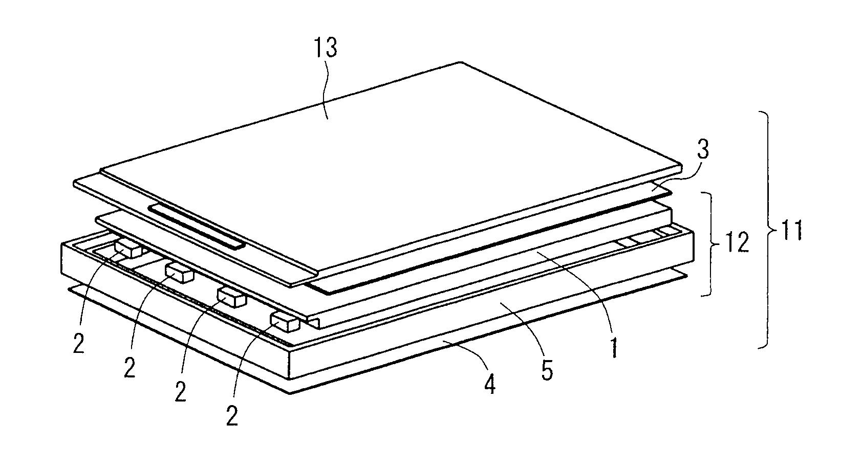
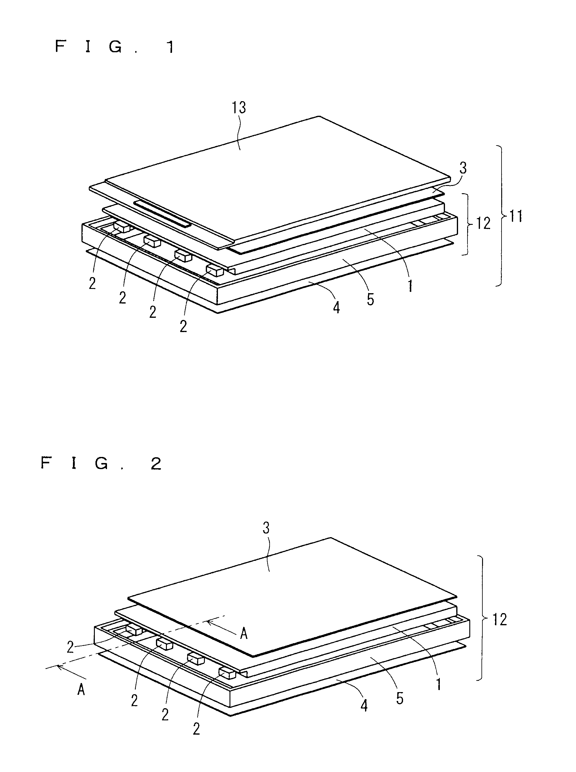
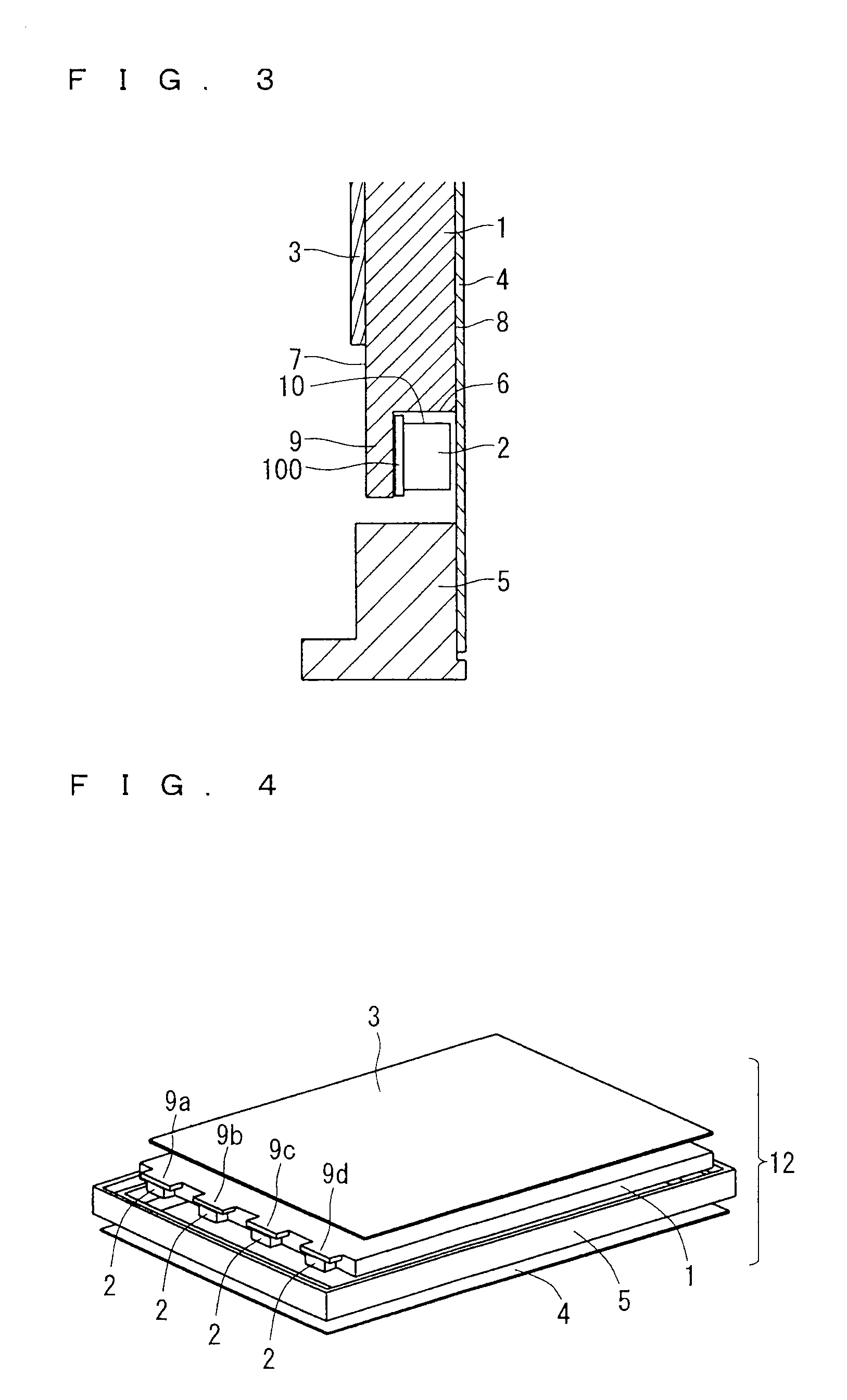
[0025]FIG. 1 is a perspective view showing a configuration of a display device 11 including a surface light source device 12 according to this preferred embodiment, and FIG. 2 is a perspective view showing a configuration of the surface light source device 12 according to this preferred embodiment. FIG. 3 is a partial cross-sectional view of the surface light source device 12, which is taken along the direction A-A of FIG. 2.
[0026]As shown in FIG. 2, the surface light source device 12 includes a light guide plate 1 formed of a transparent acrylic resin, one or a plurality of point light sources 2 disposed to the light guide plate 1, an optical sheet 3 provided on a front surface of the light guide plate 1, a reflective sheet 4 provided on the back surface of the light guide plate 1, and a casing 5 that encloses the light guide plate 1 and the point light sources 2.
[0027]With reference to FIG. 3, the light guide plate 1 includes an incidence surface 6 on which the light beams f...
second preferred embodiment
[0046]
[0047]FIG. 5 is a perspective view showing the configuration of the display device 11 including the surface light source device 12 according to this preferred embodiment, and FIG. 6 is a perspective view showing the configuration of the surface light source device 12 according to this preferred embodiment. FIG. 7 is a partial cross-sectional view of the surface light source device 12, which is taken along the A-A direction of FIG. 6. While the eaves portion 9 is disposed such that the upper surface of the eaves portion 9 is flush with the exit surface 7 of the light guide plate 1 in the first preferred embodiment, in the second preferred embodiment, an eaves portion 90 is disposed in such a step manner as to be higher than the exit surface 7. The configuration other than the eaves portion 90 is similar to that of the first preferred embodiment, and thus description thereof is omitted.
[0048]The eaves portion 90 is provided outside the display area of the liquid crystal panel 13...
third preferred embodiment
[0054]
[0055]FIG. 9 is a perspective view showing the configuration of the surface light source device 12 according to this preferred embodiment. FIG. 10 is a partial cross-sectional view of the surface light source device 12, which is taken along the A-A direction of FIG. 9. While the eaves portion 9, 90 is disposed only on the exit surface 7 side of the light guide plate 1 in the first, second preferred embodiment, in the third preferred embodiment, a first eaves portion 91 and a second eaves portion 92 are formed on the exit surface 7 side and the reflective surface 8 side of the incidence surface of the light guide plate 1, as shown in FIGS. 9 and 10. The configuration other than the eaves portions 91 and 92 is similar to that of the first preferred embodiment, and thus description thereof is omitted.
[0056]On the incidence surface 6 of the light guide plate 1, the first eaves portion 91 and the second eaves portion 92 are provided on the exit surface 7 side and the reflective sur...
PUM
 Abstract
Description
Claims
Application Information
 - R&D
- Intellectual Property
- Life Sciences
- Materials
- Tech Scout
- Unparalleled Data Quality
- Higher Quality Content
- 60% Fewer Hallucinations
Browse by: Latest US Patents, China's latest patents, Technical Efficacy Thesaurus, Application Domain, Technology Topic, Popular Technical Reports.
© 2025 PatSnap. All rights reserved.Legal|Privacy policy|Modern Slavery Act Transparency Statement|Sitemap|About US| Contact US: help@patsnap.com


