Direct magnetic imaging apparatus and method
a direct magnetic imaging and apparatus technology, applied in the direction of reradiation, measurement using nmr, instruments, etc., can solve the problems of inability to individually resolve small anatomical features, inability to obtain spatial information, and long wavelengths
- Summary
- Abstract
- Description
- Claims
- Application Information
AI Technical Summary
Problems solved by technology
Method used
Image

Examples
second embodiment
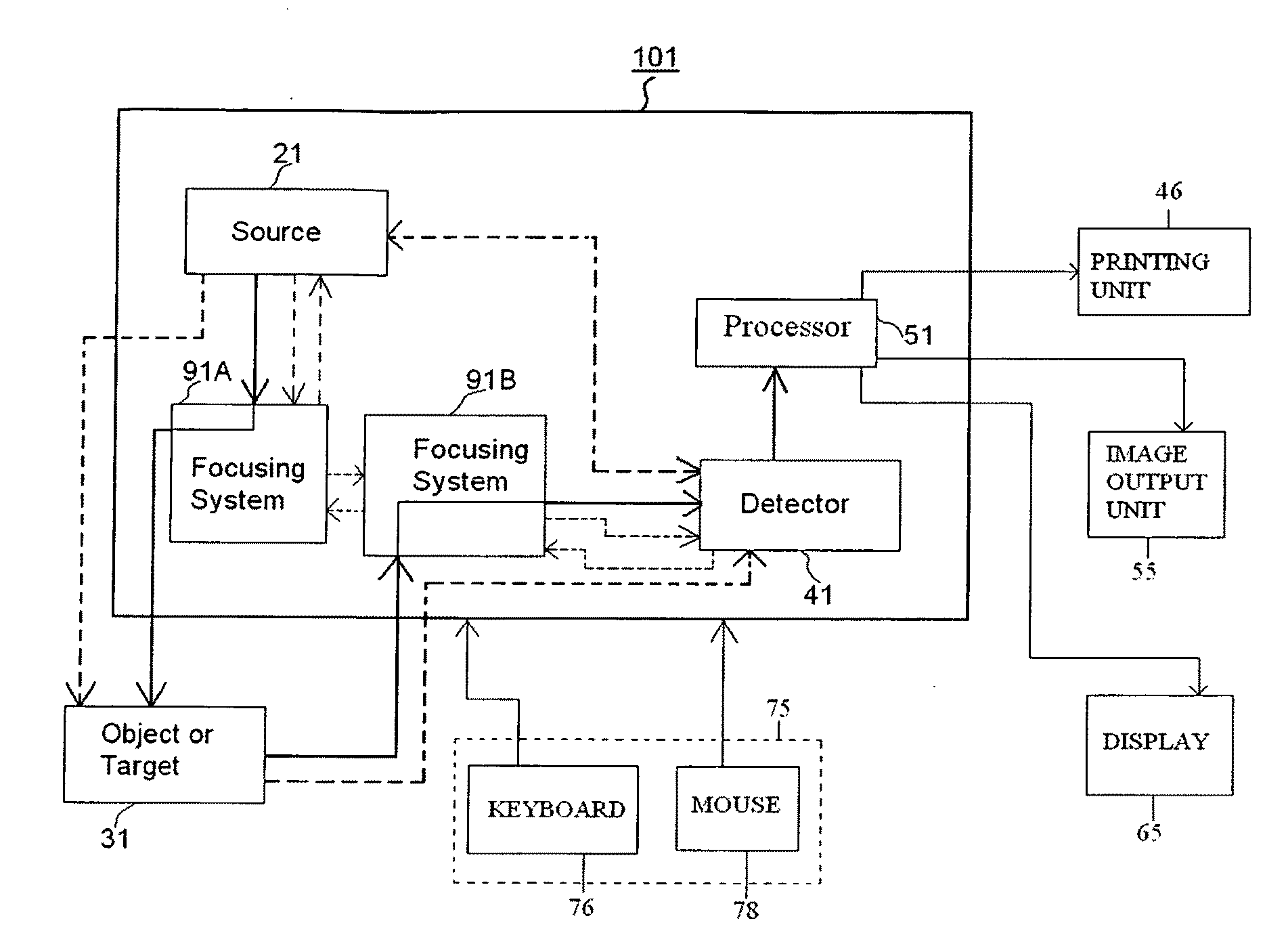
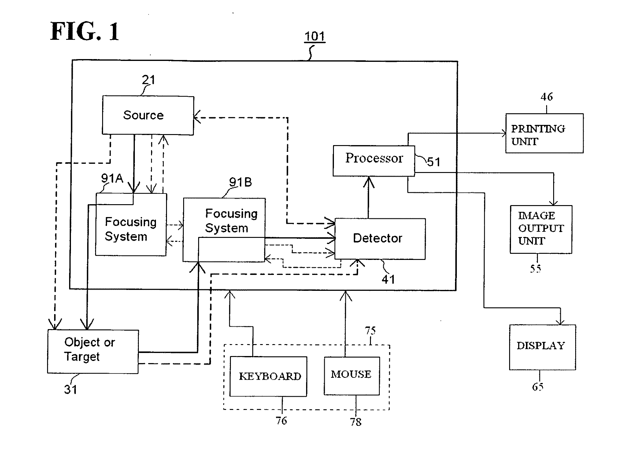
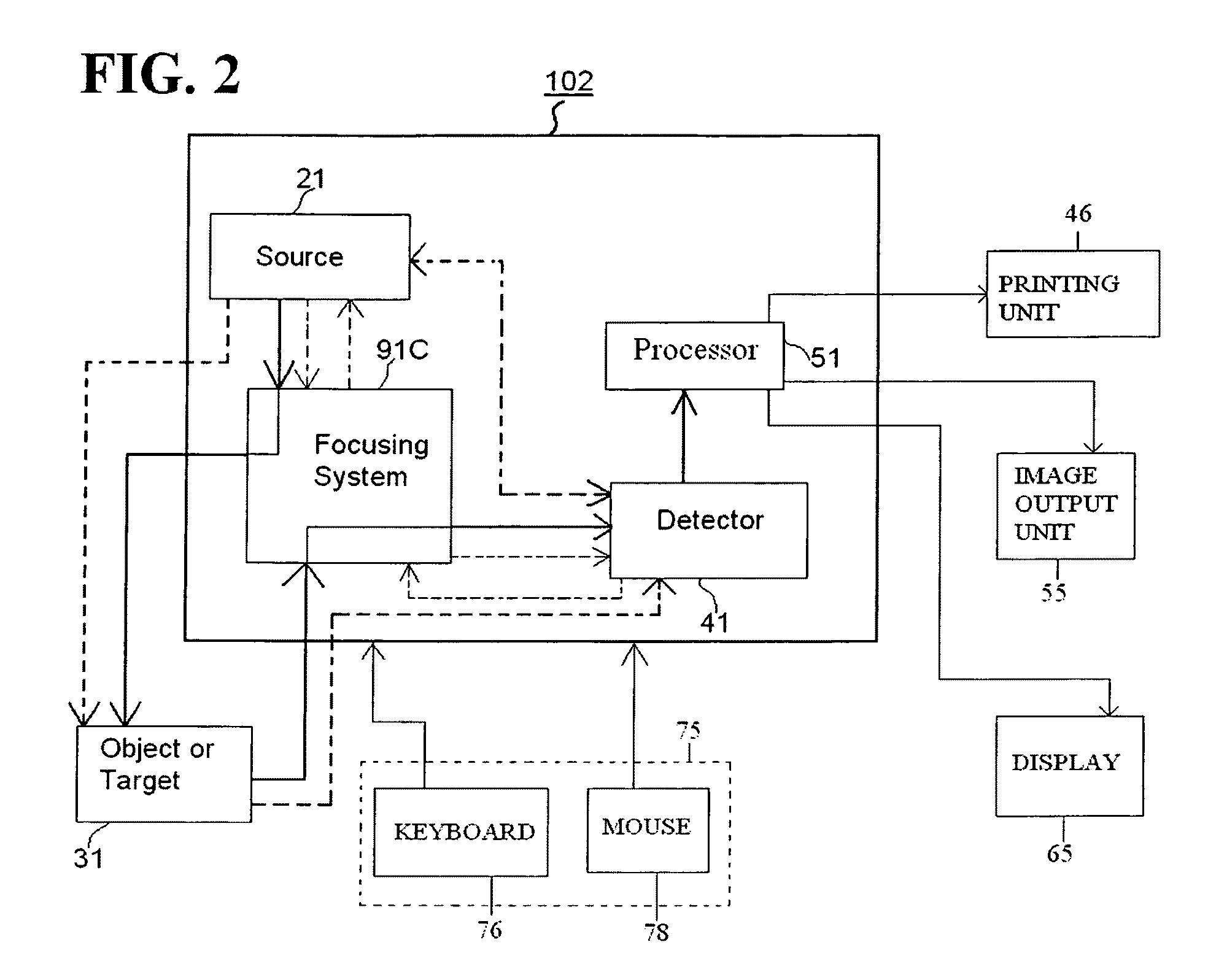
[0049]FIG. 2 is a general block diagram of a Direct Magnetic Imager 102 according to the present invention. The system 102 illustrated in FIG. 2 includes the following components: a source 21; a focusing system 91C; a detector 41; and a processor 51. Focusing system 91C is in the path of the electromagnetic field created by source 21 and performs a focusing function on the field / radiation / signal onto the object / target 31. Focusing system 91C also receives a signal, radiation, or field signature from object / target 31 and focuses it onto detector 41.
[0050]Detector 41 performs analysis of the received data, and outputs the results to processor 51, which outputs a representation, such as, for example, a graphical representation of the imaged object or target area, or other type of reconstruction data.
[0051]In one embodiment, a first signal / radiation / field from source 21 directly reaches object / target 31, while a second signal / radiation / field from source 21 is focused through focusing sy...
third embodiment
[0053]FIG. 3 is a general block diagram of a Direct Magnetic Imager 103 according to the present invention. The Direct Magnetic Imager 103 illustrated in FIG. 3 includes: a source 21; focusing systems 91D and 91E; a detector 41; a processor 51; and a control unit 99. FIG. 4 is a general block diagram of a Direct Magnetic Imager 104 according to another embodiment of the present invention. The Direct Magnetic Imager 104 illustrated in FIG. 4 includes: a source 21; a focusing system 91F; a detector 41; a processor 51; and a control unit 99.
[0054]In accordance with these third and fourth embodiments of the present invention, the source 21, focusing systems 91D, 91E and 91F, detector 41 and processor 51 may function in like manner to the corresponding elements of the first and second embodiment. In accordance with the third and fourth embodiments illustrated in FIGS. 3 and 4, control unit 99 controls one or more of the following units: focusing systems 91D, 91E and 91F, source 21 and de...
PUM
 Abstract
Description
Claims
Application Information
 - R&D
- Intellectual Property
- Life Sciences
- Materials
- Tech Scout
- Unparalleled Data Quality
- Higher Quality Content
- 60% Fewer Hallucinations
Browse by: Latest US Patents, China's latest patents, Technical Efficacy Thesaurus, Application Domain, Technology Topic, Popular Technical Reports.
© 2025 PatSnap. All rights reserved.Legal|Privacy policy|Modern Slavery Act Transparency Statement|Sitemap|About US| Contact US: help@patsnap.com