Circuit Arrangement Including a Multi-Level Converter
a converter and circuit technology, applied in the direction of dc-ac conversion without reversal, battery/fuel cell control arrangement, electric devices, etc., can solve the problem of adding to the complexity of the system
- Summary
- Abstract
- Description
- Claims
- Application Information
AI Technical Summary
Problems solved by technology
Method used
Image
Examples
Embodiment Construction
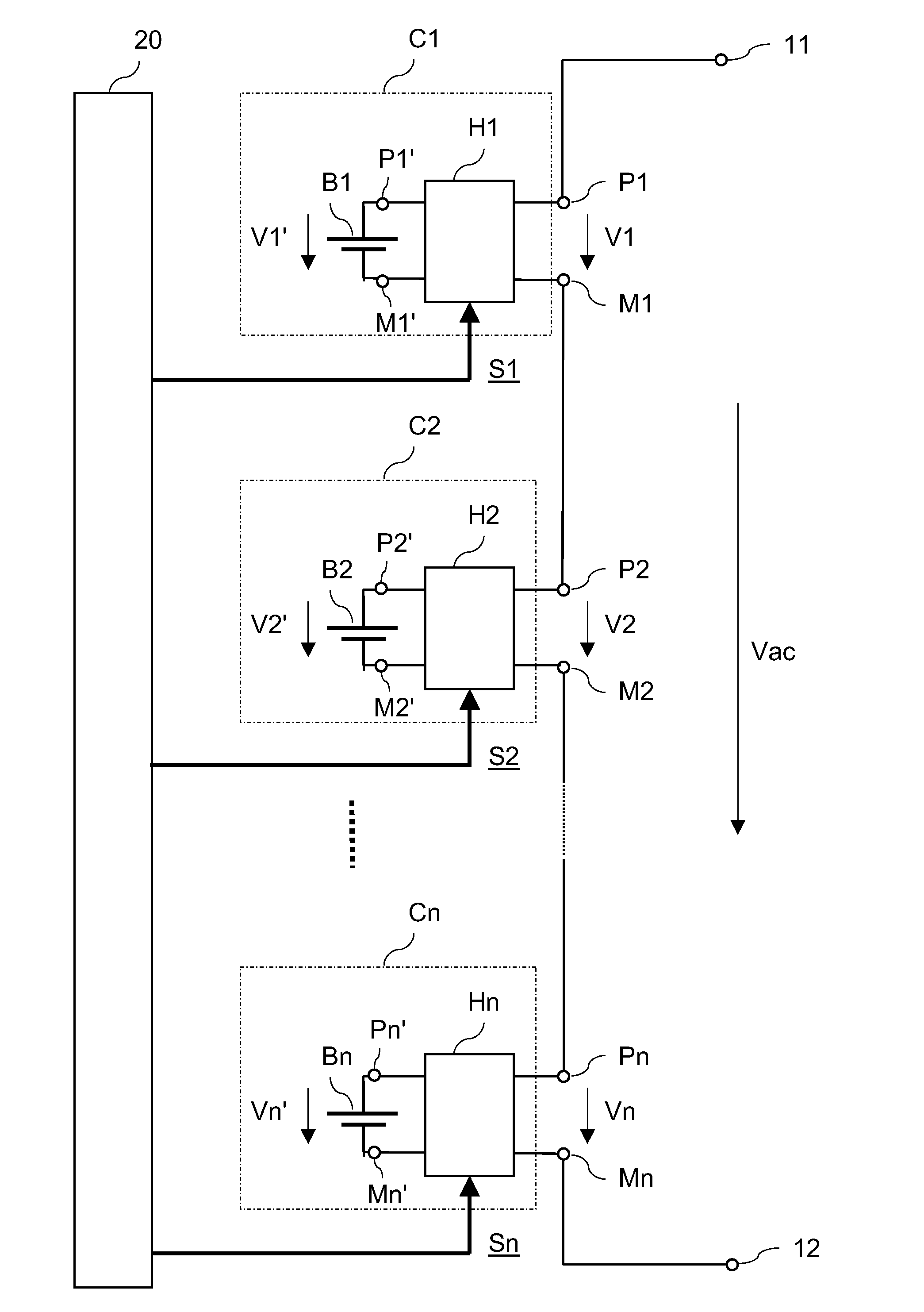
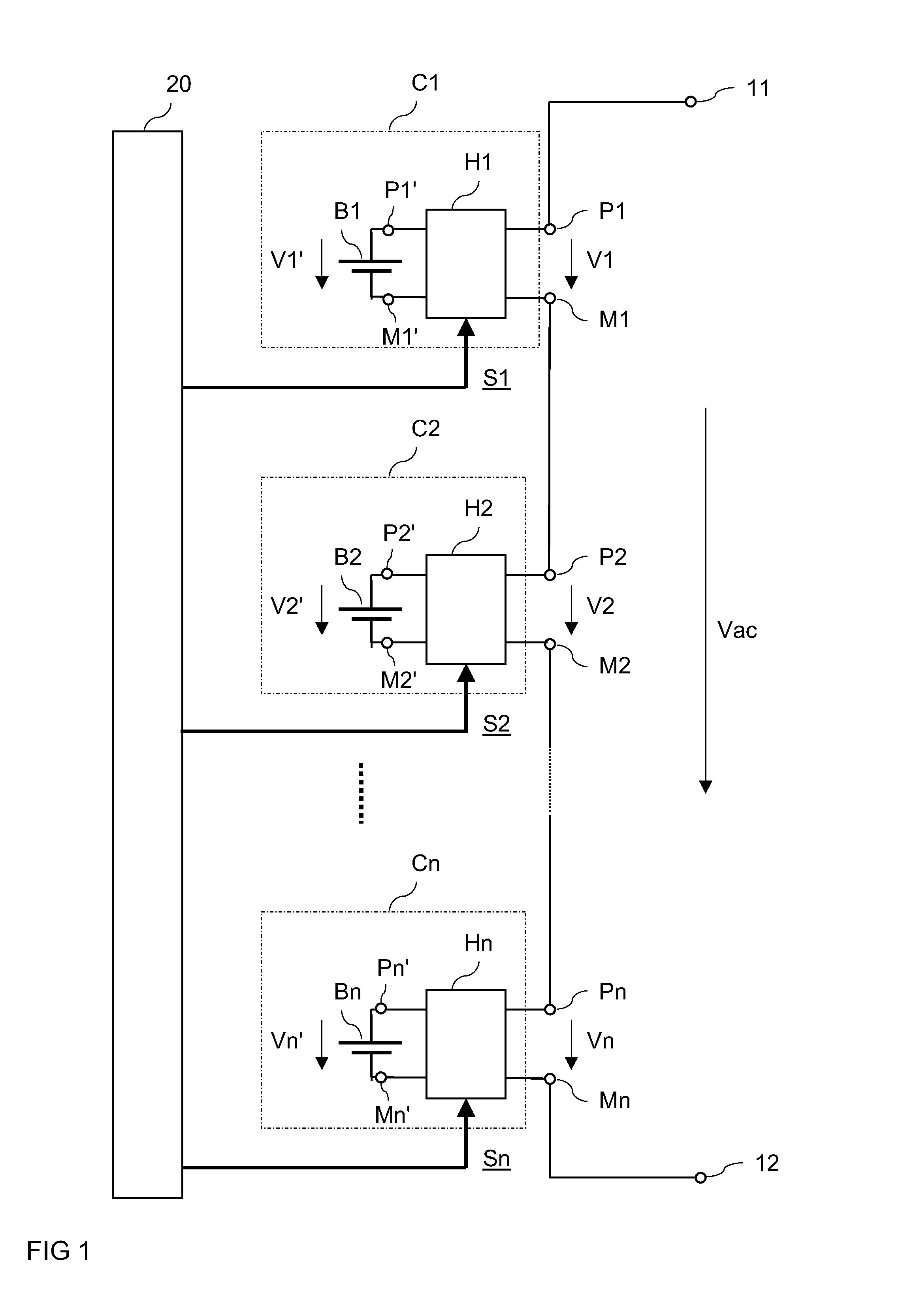
[0027]FIG. 1 schematically illustrates a circuit arrangement that includes a multi-level converter. The multi-level converter includes voltage supply terminals 11, 12 adapted to provide an AC output voltage Vac, and a plurality of at least two converter units. In the present example the multi-level converter includes three converter units C1, C2, Cn. However, this is only an example. It goes without saying that any number higher than one of converter units can be provided.
[0028]Each of the converter units C1, C2, Cn includes: input terminals P1′, M1′, . . . , Pn′, Mn′ that are adapted to have an electrical charge storage unit B1, B2, Bn connected thereto; output terminals P1, M1, P2, M2, Pn, Mn; and a switch arrangement H1, H2, Hn connected between the input and the output terminals. Each of the switch arrangements H1, H2, Hn receives a control signal S1, S2, Sn and is adapted to provide a pulse-width modulated output voltage V1, V2, Vn at the output terminals P1, M1, P2, M2, Pn, Mn...
PUM
 Abstract
Description
Claims
Application Information
 - R&D
- Intellectual Property
- Life Sciences
- Materials
- Tech Scout
- Unparalleled Data Quality
- Higher Quality Content
- 60% Fewer Hallucinations
Browse by: Latest US Patents, China's latest patents, Technical Efficacy Thesaurus, Application Domain, Technology Topic, Popular Technical Reports.
© 2025 PatSnap. All rights reserved.Legal|Privacy policy|Modern Slavery Act Transparency Statement|Sitemap|About US| Contact US: help@patsnap.com


