
Hybrid welding with multiple heat sources

a hybrid laser welding and heat source technology, applied in the direction of plasma welding apparatus, welding equipment, manufacturing tools, etc., can solve the problems of high cost of lasers used to complete the laser hybrid welding operation, undesirable additional time required to move the hybrid laser welder or rotate the pieces of metal and make two sequential passes with welding equipment, and undesirable to operate two separate hybrid laser welders on the joint. , to achieve the effect of greater penetration

Active Publication Date: 2011-08-18
THE ESAB GROUP
View PDF18 Cites 34 Cited by
  • Summary
  • Abstract
  • Description
  • Claims
  • Application Information

AI Technical Summary

Benefits of technology

The present patent describes a method and apparatus for welding together multiple pieces of metal at an angle joint. The method involves directing high energy density heat and arc welding heat to create a common molten metal pool that solidifies to form a weld extending through the joint. The apparatus includes a high energy density heat source and an arc welding heat source, which may be a gas tungsten arc welding torch or a plasma arc welding torch. The method may also involve directing a third output from a second arc welding heat source to create a third molten metal pool that joins with the first molten metal pool. The angle joint may be formed between two pieces of metal with a chamfer or other gap between them. The technical effect of the invention is to provide a more efficient and effective method for welding angle joints between metal pieces.

Problems solved by technology

However, the additional time required to move the hybrid laser welder or rotate the pieces of metal and make two sequential passes with the welding equipment is undesirable.
Since the lasers used to complete the laser hybrid welding operation may be very expensive, it may be undesirable to operate two separate hybrid laser welders on the joint.

Method used


Image

  • Hybrid welding with multiple heat sources
  • Hybrid welding with multiple heat sources
  • Hybrid welding with multiple heat sources

Examples


Embodiment Construction

[0043]Apparatuses and methods for welding now will be described more fully hereinafter with reference to the accompanying drawings in which some but not all embodiments are shown. Indeed, the present development may be embodied in many different forms and should not be construed as limited to the embodiments set forth herein; rather, these embodiments are provided so that this disclosure will satisfy applicable legal requirements. Like numbers refer to like elements throughout.

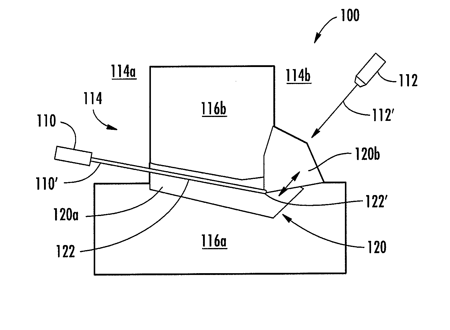
[0044]FIG. 2a illustrates a first piece of metal 116a and a second piece of metal116b which are positioned so as to form a joint 114. FIG. 2b illustrates a corresponding embodiment of a welding apparatus 100 configured to weld together the first 116a and second 116b pieces of metal at the joint 114. The welding apparatus 100 includes a high energy density heat source 110 configured to direct a first output 110′ against a first side 114a of the joint. The first output 110′ thereby produces a keyhole 122 (which ...


PUM

PropertyMeasurementUnit
energy densityaaaaaaaaaa
angleaaaaaaaaaa
angle of incidenceaaaaaaaaaa

Abstract

A method of welding a joint includes directing a first output from a high energy density heat source, such as a laser, against a first side of the joint. The method further includes directing a second output from an arc welding heat source, such as a gas metal arc welding torch, against a second side of the joint. The first output produces a keyhole surrounded by a molten metal pool which extends from the first side of the joint toward the second side of the joint. In some embodiments a third output from a second arc welding heat source may also be directed at the first side of the joint. A second molten metal pool produced by the arc welding heat source joins with the first molten metal pool and the third molten metal pool to form a common molten metal pool which solidifies to form the weld.

Description

BACKGROUND OF THE INVENTION[0001]1. Field of the Invention[0002]The present application relates to methods and apparatuses for welding together a plurality of pieces of metal at a joint between the pieces of metal.[0003]2. Description of Related Art[0004]Recently commercialized hybrid laser arc welding is a method of welding two pieces of metal together which typically combines laser beam welding with gas metal arc welding, for example, on the same side of a joint between the pieces of metal to simultaneously direct both a laser beam and an electric arc at one welding zone to produce a common molten metal pool which solidifies to form a weld. As illustrated in FIG. 1a, a prior art apparatus may accomplish this by directing the laser beam output 10′ from a laser 10 (which may comprise a laser resonator and associated optics) and the electric arc output 12′ from a gas metal arc welder 12 at the first side 14a of a joint 14 in order to weld a first piece of metal 16a to a second piece ...

Claims


Application Information

Patent Timeline
Patent Type & Authority Applications(United States)
IPC IPC(8): B23K9/16B23K26/00B23K15/00B23K10/00B23K9/00B23K9/18
CPCB23K9/16B23K10/02B23K15/006B23K2201/18B23K26/243B23K28/02B23K26/1429B23K26/242B23K26/348B23K2101/18
Inventor LIN, DECHAO
Owner THE ESAB GROUP
Learn More