
Enhanced manually actuated pressure controlled modulator technology

a technology of pressure control modulator and manual action, which is applied in the direction of respirator, respirator, respirator, etc., can solve the problems of too small gas per breath volume (tidal volume) for patients, easy misuse of manual resuscitation device, and too quick respiratory ra

Inactive Publication Date: 2011-08-18
PIPER MEDICAL
View PDF39 Cites 20 Cited by
  • Summary
  • Abstract
  • Description
  • Claims
  • Application Information

AI Technical Summary

Benefits of technology

[0020]The present invention generally comprises a pressure pulmonary modulator apparatus which will inflate and discharge any respiratory gas from a patient for a wide range of frequencies when provided with a constant flow of gas and which also has the ability to immediately provide inhalation support to a patient at a limited finite level of pressure whenever manually actuated by the clinician while requiring no more parts or cost than existing PMAs.
[0021]An object of the invention is to provide a simplified ventilator apparatus for providing constant flow, pressure cycled ventilatory support to patients and that allows immediate manual initiation of inspiration support.
[0022]Another object of the invention is to provide a simplified ventilator apparatus that provides constant flow, pressure cycled ventilatory support and that allows for easy detection of the sedative state of the patient.

Problems solved by technology

Unfortunately, manual resuscitators are easy to misuse.
A large number of studies have been published which show that irregardless whether the operator of the manual resuscitator is a physician, respiratory therapist or nurse, patients receive volumes of gas per breath (tidal volume) which are too small and respiratory rates which are too quick.
This has been shown to create significant adverse effects on patients.
Lung compliance is prone to sudden changes during transport, potentially causing patient airway pressures to increase to the point that they will severely injure the patient.
Although current transport ventilators provide consistent, safe and reliable ventilation, they are extremely expensive.
These devices are often classified as automatic resuscitators and, in addition to not being as safe, still cost thousands of dollars and require the use of additional disposable or parts which require sterilization before being reused.
In today's environment of medical cost containment, hospitals and other medical providers have, for the most part, balked at the cost of transport ventilators and the training of additional personnel it would require.
Unfortunately a PMA has a number of problems: 1. it can stop cycling due to physiological, mechanical, pneumatic, or environmental changes; 2. it can be hard or impossible for a user to determine if the device is automatically cycling or if the patient is initiating breathing thus increasing the work of breathing for the patient; 3. it is limited to delivering a set level of PEEP that is a constant ratio of PIP; and 4. it has no means of providing an inspiratory hold.
Although this has the benefit of alerting the clinician that the situation is changing, the condition is ultimately highly undesirable because the patient still needs ventilatory support and the only manner that ventilatory support may be provided by existing PMAs is by the clinician determining what change occurred and changing the baseline settings of the PMA to compensate.
Determining what change occurred can be time consuming, and if the patient is not being provided ventilatory support, clinicians are rushed and almost always don't have the time.
Furthermore, changing the baseline settings of the PMA is often undesirable because it creates a greater degree of uncertainty in a situation that may still be varying and problematic, thus re-stabilizing the patient becomes more difficult.
Maintaining the patient in a sedated state can sometimes be problematic because the effects of the medication can subside, or if the medication has just recently been administered, it will take time for the medication to take effect.
Determining which state the patient is in is very difficult to do with the existing PMA design because it is impossible to tell if the patient or the device is causing the cycling of the PMA.
Since some patients may require additional PEEP beyond what is provided for a set PIP, this is a serious limitation of the PMA.
Currently, the PMA may be set to deliver an increased PEEP by adjustment of the rate dial or by increasing flow, but this places the device in a mode that will not cycle unless initiated by the patient which is clearly undesirable the vast majority of the time because it increases the work of breathing of the patient and the patient may simply be unable to make the respiratory effort.
The situation can be rectified by addition of an in-line PEEP valve placed between the inlet of the modulator and the patient's airway, but this adds to the cost and clumsiness of the device, and is not practical since additional PEEP is only needed sometimes and as a result clinicians are not likely to keep such devices on hand.
Current PMAs do not have this capacity without inducing major clinical inconvenience and disturbance.
One method currently employed using existing PMAs is to create a condition in which the entire exhalation path is occluded, potentially leading to damaging pressure levels, and failing to provide a sustained pressure level support.
As a result, there is sometimes a reluctance to employ existing PMAs because there is a fear that the EMT may face a situation in which they are not entirely sure what the most appropriate adjustment would be in the event that the PMA stops delivering ventilatory support for mechanical or physiological reasons.
Existing PMAs don't have any readily available way to provide these clinicians with a simple back up plan in such event.

Method used


Image

  • Enhanced manually actuated pressure controlled modulator technology
  • Enhanced manually actuated pressure controlled modulator technology
  • Enhanced manually actuated pressure controlled modulator technology

Examples


Embodiment Construction

[0107]While the present invention is susceptible of embodiment in various forms, there is shown in the drawings and will hereinafter be described a presently preferred embodiment of the invention, with the understanding that the present disclosure is to be considered as an exemplification of the invention, and is not intended to limit the invention to the specific embodiment illustrated.

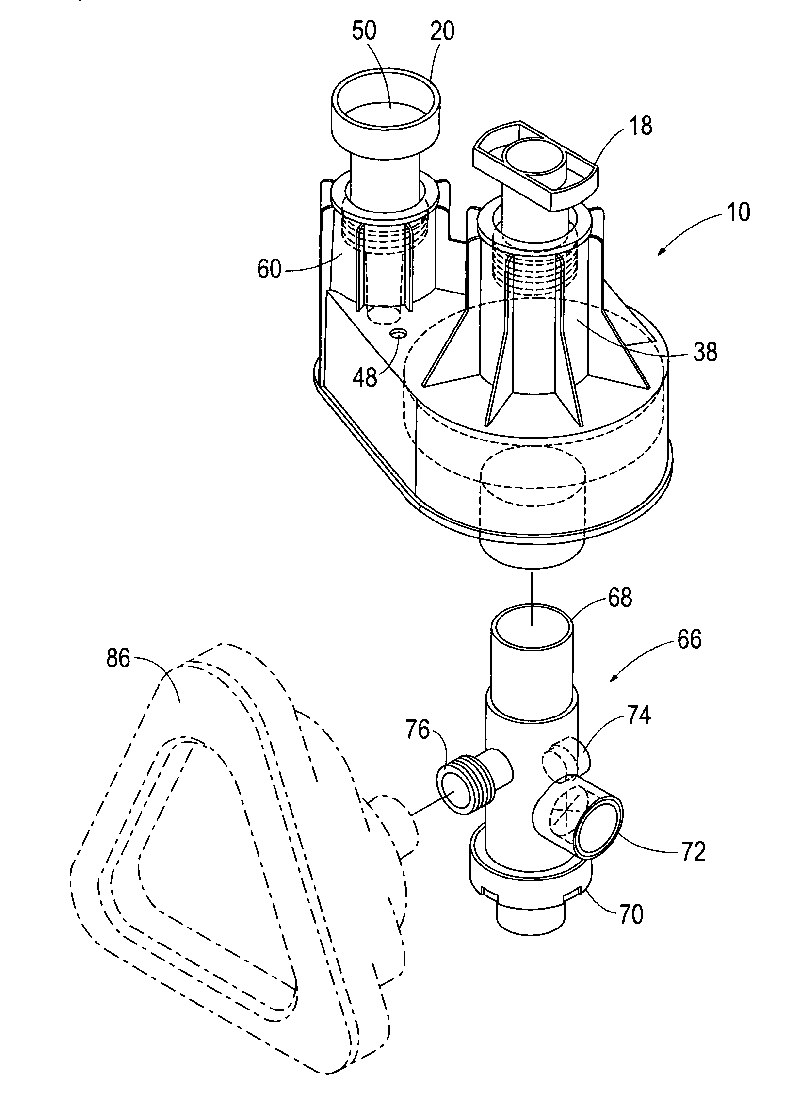
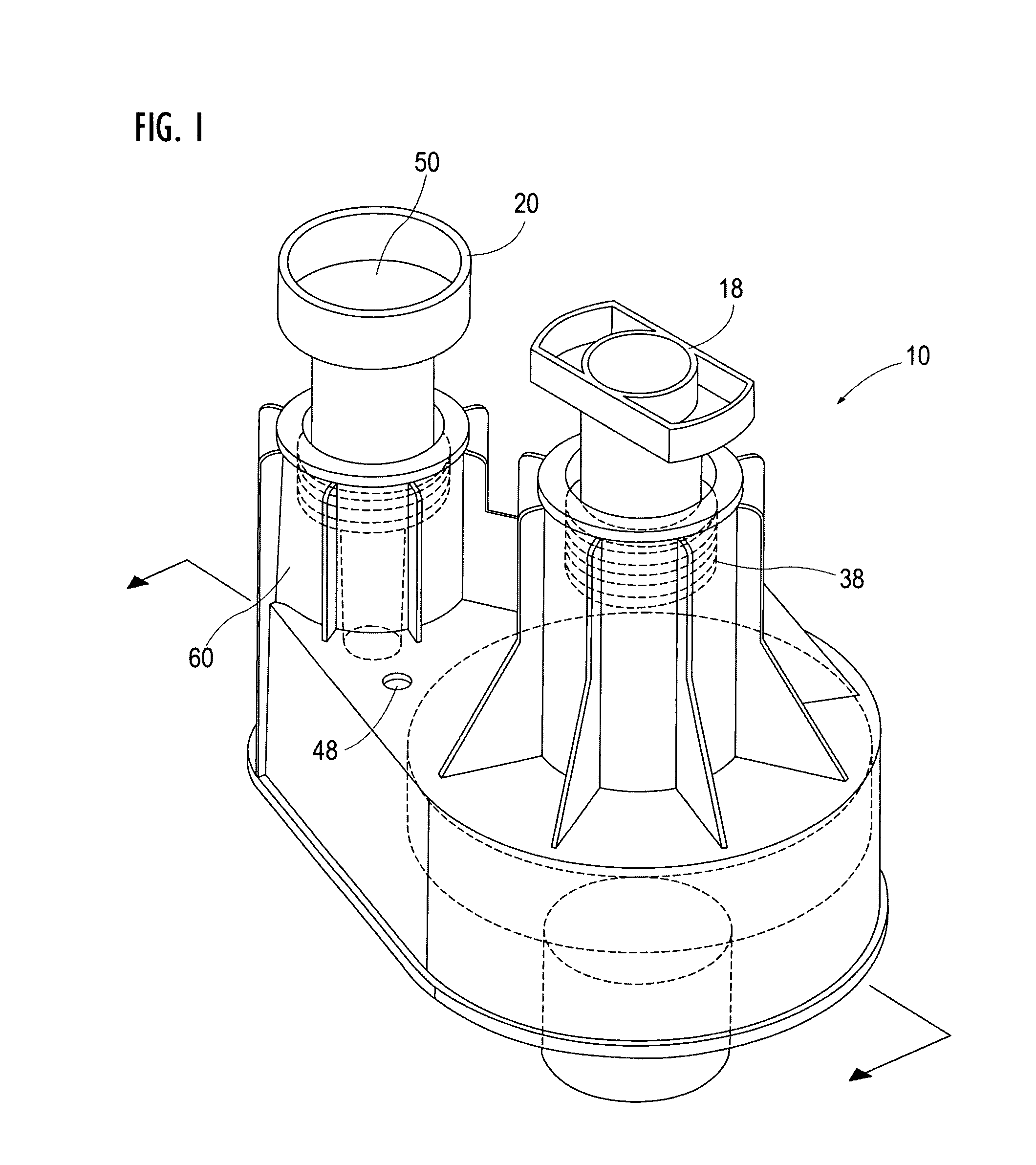
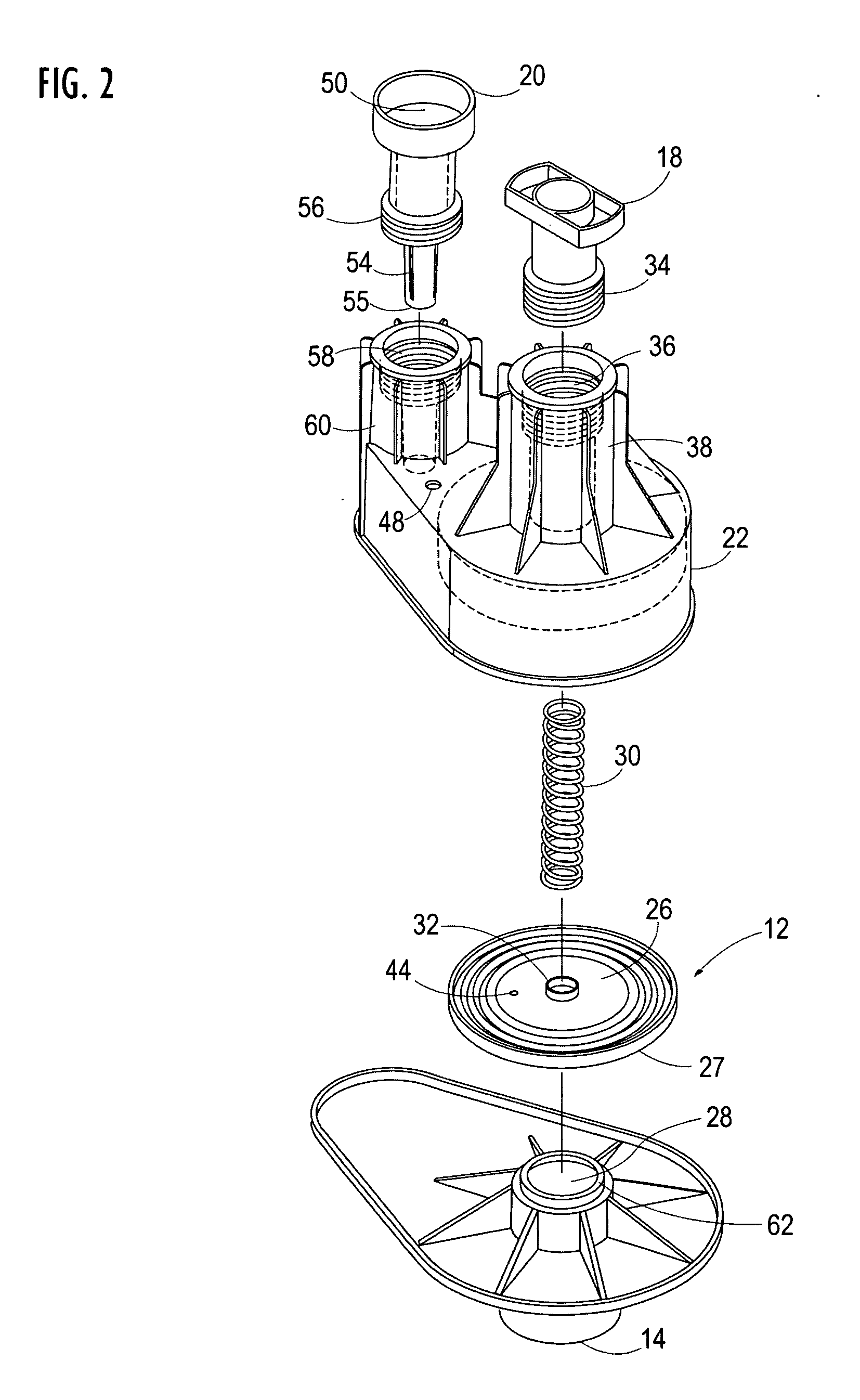
[0108]For illustrative purposes the present invention is embodied in the apparati generally shown in FIG. 1 through 7. It will be appreciated that the apparatus may vary as to configuration and as to details in the parts without departing from the basic concepts as disclosed herein.

[0109]Referring first to FIG. 1, FIG. 2, and FIG. 3 a constant flow, pressure modulator apparatus 10 in accordance with the preferred embodiment of the present invention is generally shown. As will be seen, the apparatus comprises a spring-loaded diaphragm assembly 12, an inlet chamber 14, a flow restrictor conduit 16, a p...


PUM


Abstract

A dual area pressure pulmonary modulator apparatus which provides constant flow, pressure cycled ventilatory support to patients that is additionally equipped with fluid conduits in the valve mechanism and body that allow the clinician or user to manually actuate inhalation by occluding a fluid path emanating from the modulator. Such feature is useful for when the device stops cycling due to physiological changes of the patient, for determining if the patient is cycling the device or if the device is automatically cycling by nature of its setting, coordinating medical procedures with the breathing of the patient, increasing the PEEP beyond the intrinsic design PEEP of the device for a given PIP setting, increasing inspiratory hold time, and providing an easy to use alternative mode of operation for users with less sophistication.

Description

CROSS-REFERENCE TO RELATED PATENTS[0001]This application claims the benefit under 35 U.S.C. 119(e) of U.S. provisional application Ser. No. 61 / 337,989 filed Feb. 12, 2010, which is incorporated by reference herein in its entirety.STATEMENT REGARDING FEDERALLY SPONSORED RESEARCH[0002]Not ApplicableBACKGROUND OF THE INVENTION[0003]1. Field of the Invention[0004]This invention pertains generally to respiratory ventilation devices with a constant flow pulmonary modulator and equipped with a manually actuating feature, and more specifically to respiratory ventilation devices with a constant flow pulmonary modulator, as described in U.S. Pat. No. 6,067,984, equipped with a feature to allow the clinician or user to easily manually activate inhalation, thus allowing a user to: 1. cycle the device and initiate inhalation immediately in the event that the device stops providing ventilatory supports and “stalls”; 2. detect if the device is automatically cycling or if the patient is triggering ...

Claims


Application Information

Patent Timeline
IPC IPC(8): A61M16/20
CPCA61M16/20A61M16/208A61M16/0833A61M16/0866A61M16/209
Inventor KOLEDIN, MICHAEL
Owner PIPER MEDICAL
Learn More