Eureka AIR delivers breakthrough ideas for toughest innovation challenges, trusted by R&D personnel around the world.

Solving a Solute Lubrication Equation for 3D Droplet Evaporation on a Complicated OLED Bank Structure

a lubrication equation and droplet technology, applied in the field of systems and methods for simulating the evaporation of droplets, can solve problems such as invalid assumption

Inactive Publication Date: 2011-08-11
SEIKO EPSON CORP
View PDF19 Cites 6 Cited by
  • Summary
  • Abstract
  • Description
  • Claims
  • Application Information

AI Technical Summary

Benefits of technology

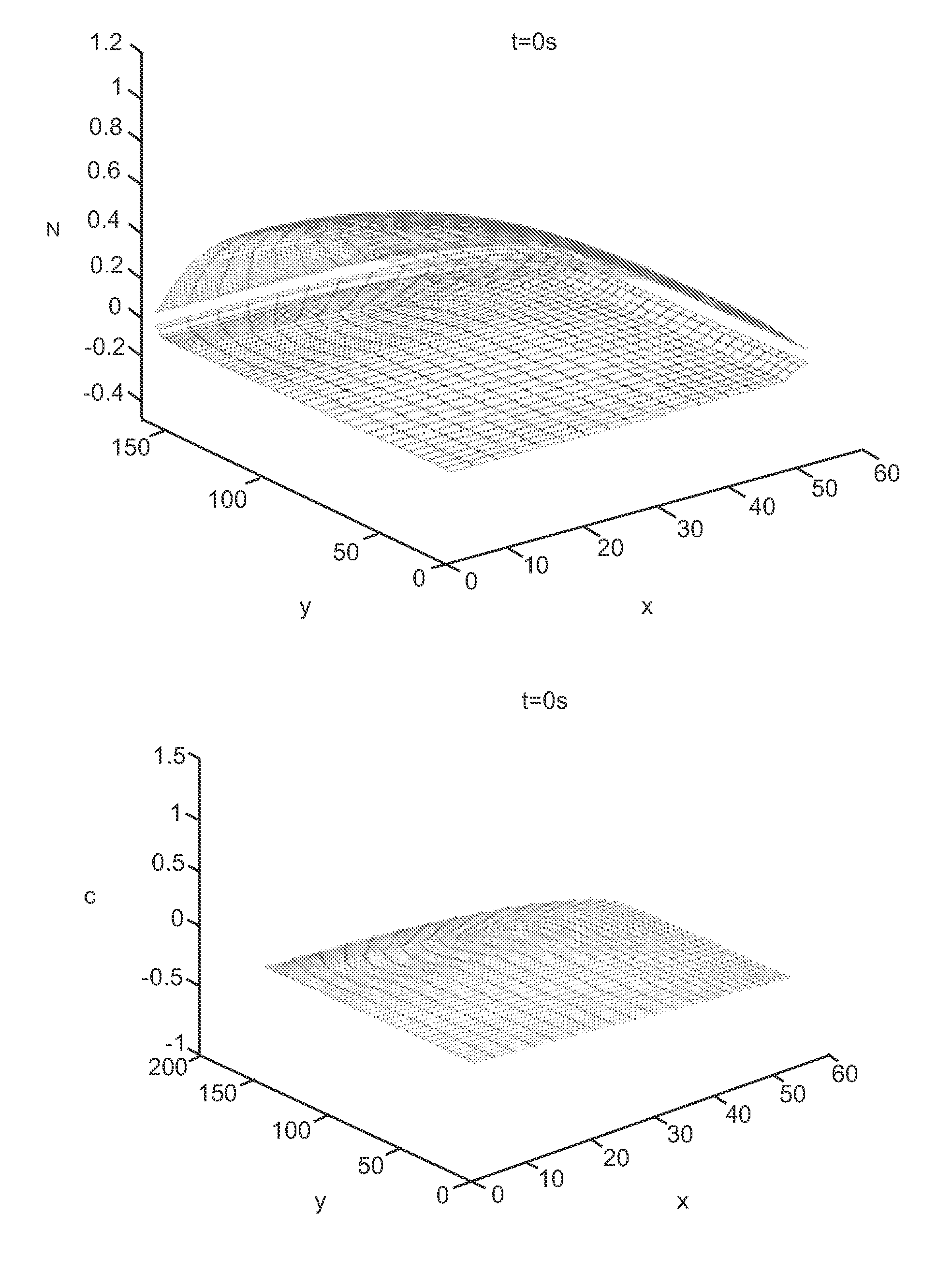
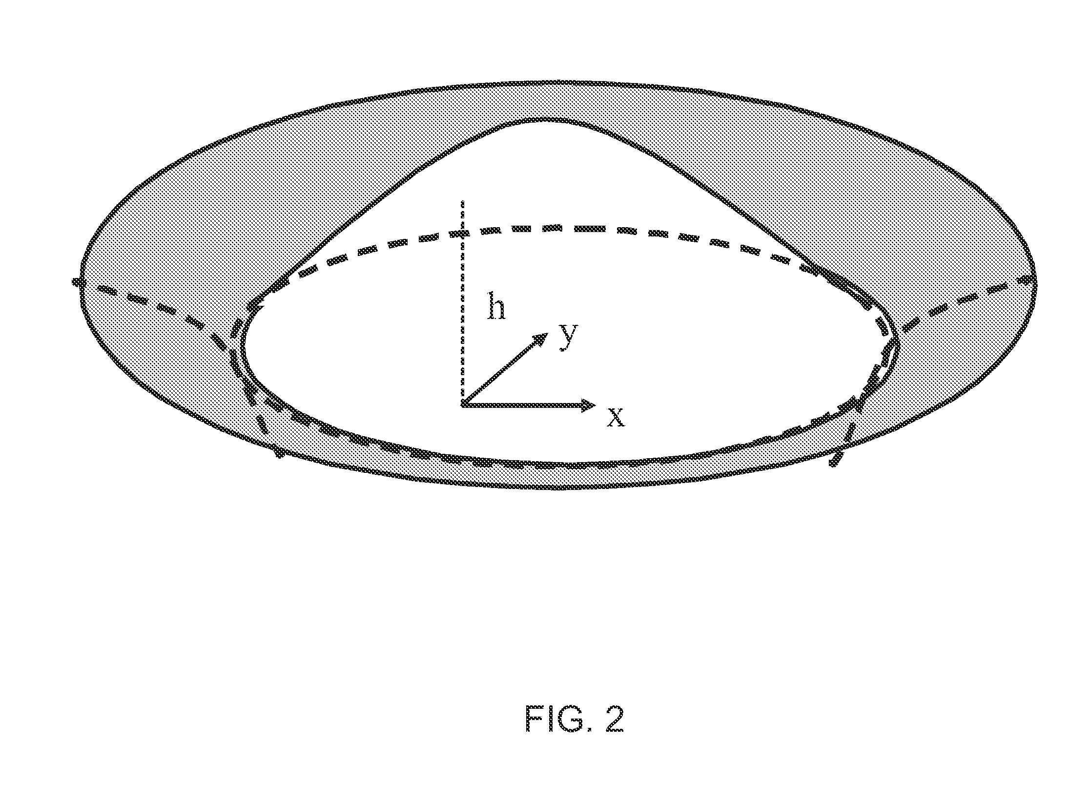
[0014]Evaporation in the droplet may be calculated using a first high-order differential function that is representative of the behavior of the height function. The first function is representative of a temporal derivative of the height function (H). The first function is equated to a second function that includes a first term that is a function of the depth function (H-f) of the droplet relative to the substrate (f) and a Laplacian of the height function (∇2H) of the droplet above the plane.
[0015]The second function may include a second term that is representative of the evaporation rate of the droplet (J). The diffusion in the droplet is calculated using a second high order differential function that is representative of the behavior of a concentration (C) of solute in the droplet. A temporal derivative of the product of a height of the droplet above the substrate and the concentration ((H-f)C) is equated to a sum of a third function and a fourth function. The third function is a differential function of a product of: the concentration (C), the depth of the droplet (H-f), and a third high order differential function of the height of the droplet (H) above a plane. The fourth function is a differential function of a product of: a differential function of the concentration (C); and the height of the droplet above the substrate (H-f).

Problems solved by technology

This assumption is invalid when the surface is not flat.

Method used


Image

  • Solving a Solute Lubrication Equation for 3D Droplet Evaporation on a Complicated OLED Bank Structure
  • Solving a Solute Lubrication Equation for 3D Droplet Evaporation on a Complicated OLED Bank Structure
  • Solving a Solute Lubrication Equation for 3D Droplet Evaporation on a Complicated OLED Bank Structure

Examples


Embodiment Construction

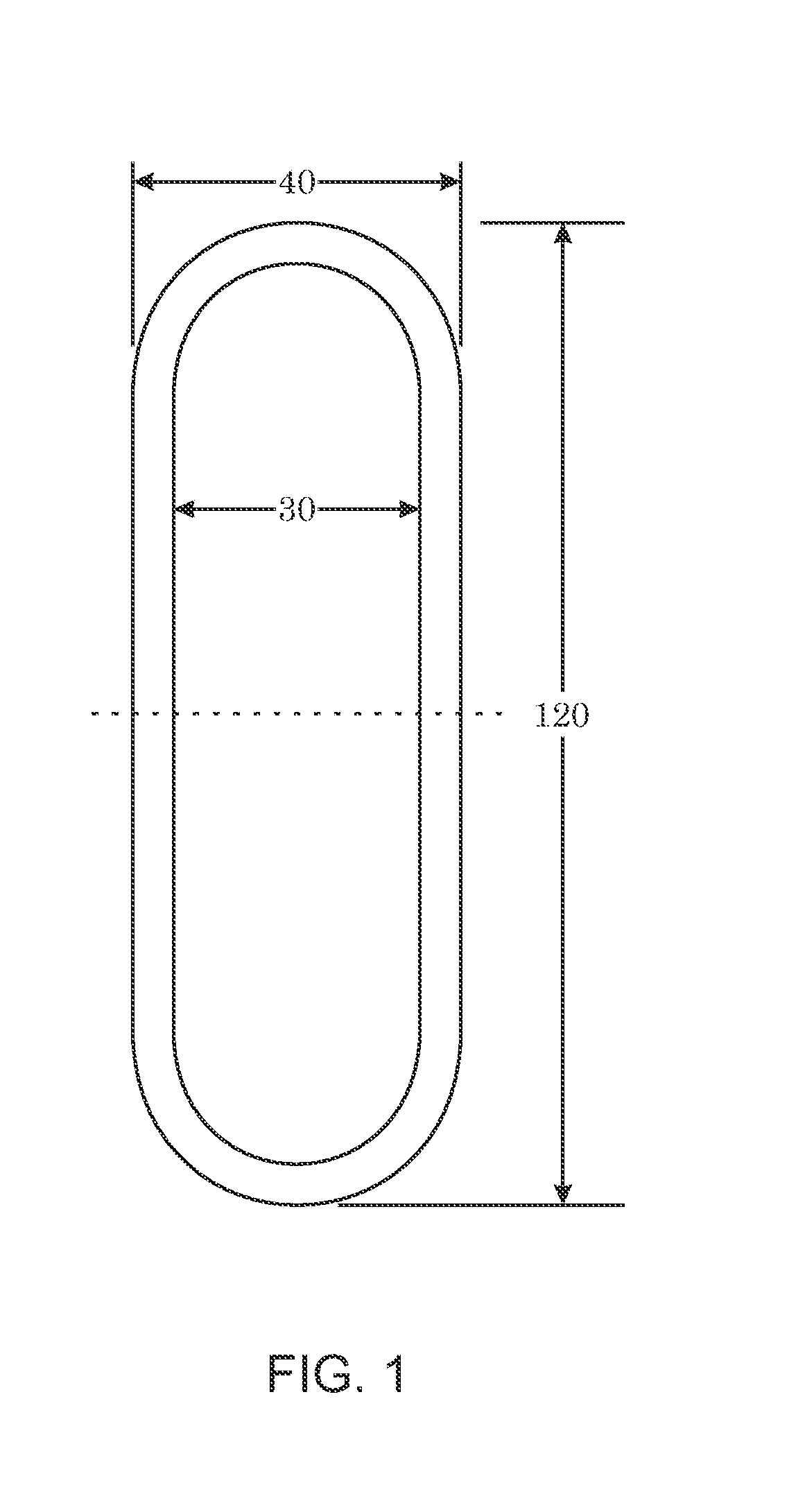
[0029]This present invention is a method based in part on the Finite Element Method (FEM) of simulating a droplet on non-flat substrate. An embodiment of the present invention may be used to simulate a droplet whose dimensions may not be reduced using symmetry.

[0030]In the industrial printing process, small ink droplets containing one or more solvents and solutes of desired metal, polymer, or other material(s) are ejected onto the target area of a patterned substrate. After the droplets land onto the targeted area, the solvent evaporates and a thin film of the solute is formed. Being able to control the final pattern of the solute film is important to the application of such industrial printing process. In order to control the final pattern of the solute film, it is crucial to understand how the final pattern is influenced by control factors like evaporation rate, initial droplet volume and shape, initial solute concentration, and contact line dynamics.

[0031]Numerical simulations ar...


PUM


Abstract

The present invention is directed to simulating a droplet of a fluid, and may be embodied in a system, method or a computer-readable medium encoded with instructions for a processor to carry out such simulation. The present invention may evaluate differential equations, which may represent an approximation of behavior over time of the droplet on a non-flat substrate. The behavior that the differential equations represent may include diffusion in the droplet and evaporation of the droplet.

Description

CROSS-REFERENCE TO RELATED APPLICATIONS[0001]The present application is related to following U.S. patent applications: U.S. patent application Ser. No. 12 / 476,588, filed on Jun. 2, 2009, entitled “A Finite Difference Algorithm for Solving Lubrication Equations with Solute Diffusion” (Attorney Docket No. AP357HO); U.S. patent application Ser. No. 12 / 411,810, filed on Mar. 26, 2009, entitled “A Finite Element Algorithm for Solving a Fourth Order Nonlinear Lubrication Equation for Droplet Evaporation” (Attorney Docket No. AP363HO); and U.S. patent application Ser. No. 12 / 579,645, filed Oct. 15, 2009, entitled “An Upwind Algorithm For Solving Lubrication Equations” (Attorney Docket No. AP359HO). Each such related application is incorporated by reference herein in its entirety.BACKGROUND[0002]1. Field of Invention[0003]The present application is directed toward systems and methods for simulating the evaporation of a droplet.[0004]2. Description of Related Art[0005]The industrial printing...

Claims


Application Information

Patent Timeline
Patent Type & Authority Applications(United States)
IPC IPC(8): G06F17/13
CPCG06F17/5018G06F17/13G06F30/23
Inventor ZHANG, JIEYU, JIUN-DER
Owner SEIKO EPSON CORP
Why Eureka
Eureka Blog
Learn More