
Method for planning a dental component

Active Publication Date: 2011-08-11
BIOCAD MEDICAL
View PDF11 Cites 47 Cited by
  • Summary
  • Abstract
  • Description
  • Claims
  • Application Information

AI Technical Summary

Problems solved by technology

While the above described 3D or CAD software systems and methods of creating a physical model are useful, in practice, they can be cumbersome for a dental practitioner to use.

Method used


Image

  • Method for planning a dental component
  • Method for planning a dental component
  • Method for planning a dental component

Examples


Embodiment Construction

[0033]As noted above, it is important to have an accurate physical model of the patient's mouth in order to produce an accurate restoration. It would be advantageous if such a physical model would be functionally equivalent or better than the current plaster models used by practitioners. Such a physical model would advantageously include a separate piece or die corresponding to the preparation. In addition, the steps required to create the physical model and / or prosthetics from a 3D software or CAD program are preferably kept to a minimum.

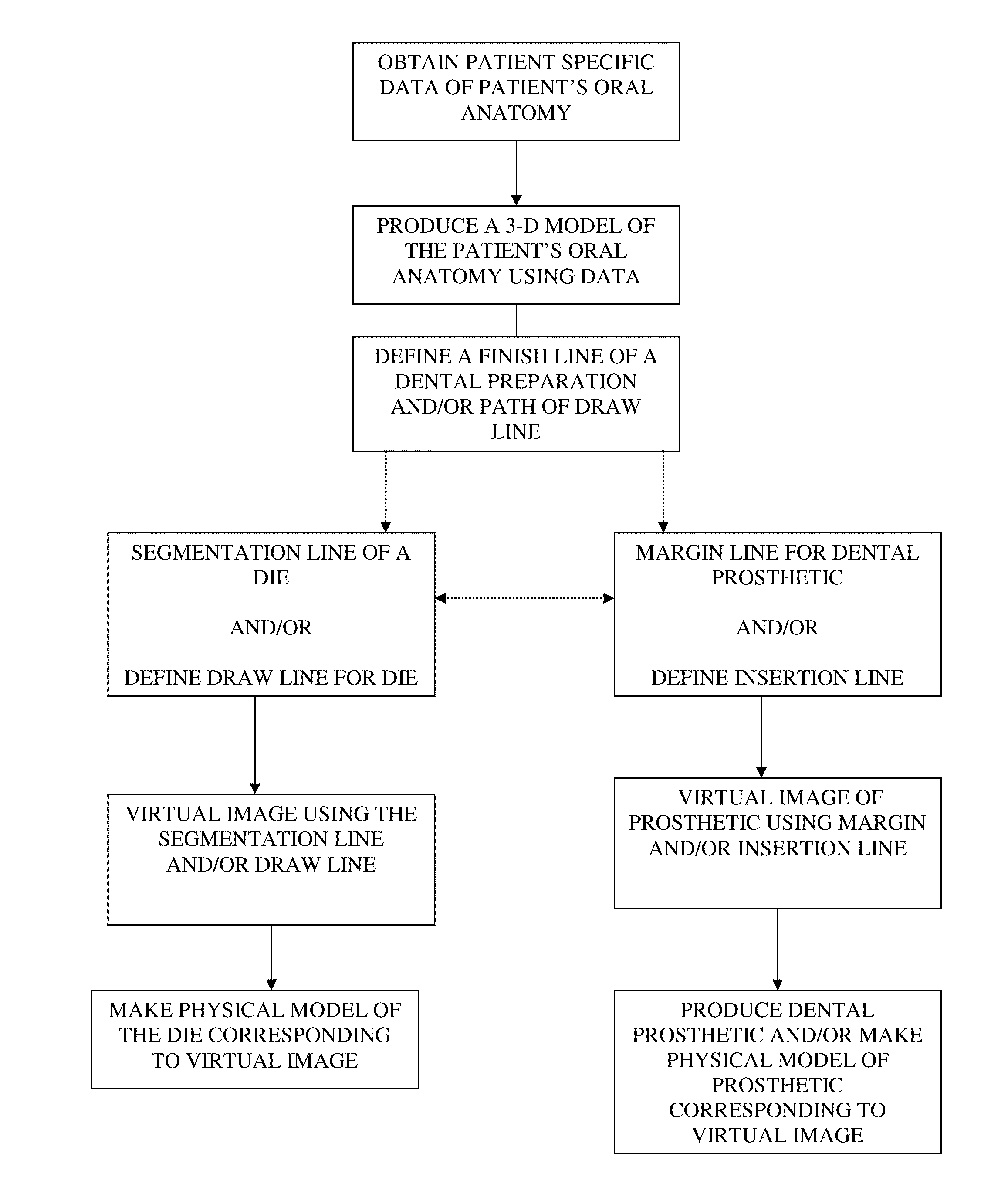
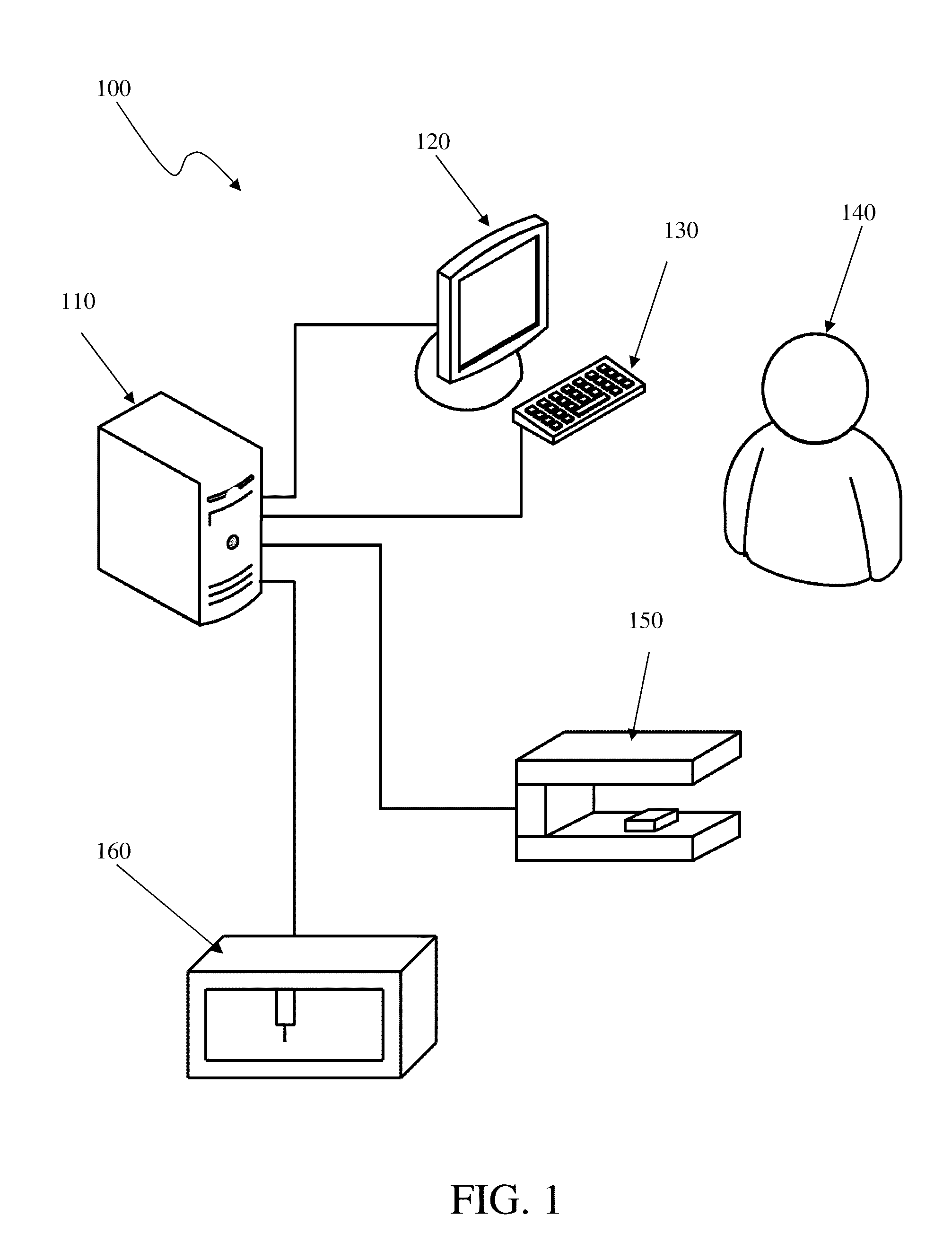
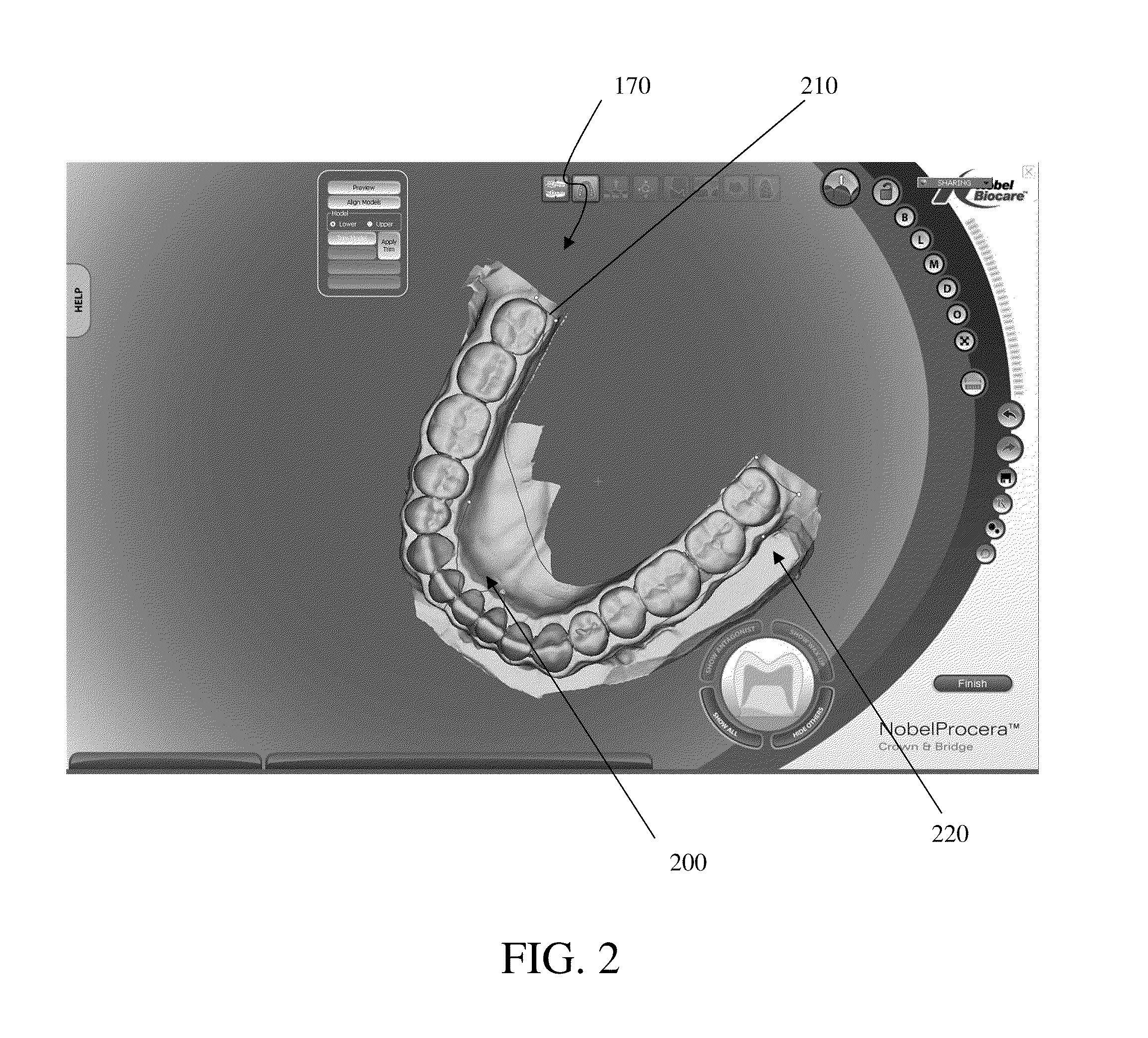
[0034]Various embodiments disclosed herein can be used to create such a physical model. For example, in one embodiment, a dental practitioner in a 3D or CAD environment can design a virtual model by using a finish line of a preparation to create a segmentation line for a die and / or a final prosthetic and / or by using a path of draw line of a die as an insertion axis line (or a basis for an insertion line) for a prosthetic that can be designed in a 3...


PUM


Abstract

Presented herein are methods and devices for designing dental components, such as physical models of a patient's anatomy, crowns and bridges. An operator of a prosthetic designing system can receive information, such as from a scanner, which provides information on the topology of the patient's dentition. The operator can use this information to design a custom prosthetic to fit the patient. Part of the designing process involves using a finish line defined for a preparation as a segmentation line for a physical die corresponding to the preparation, and using a path of draw line as an insertion axis line for a dental prosthetic.

Description

BACKGROUND[0001]1. Field of the Inventions[0002]The present application generally relates to the field of prosthodontics and more particularly to a method and apparatus for planning a dental component.[0003]2. Description of the Related Art[0004]A tooth supported artificial dental prosthetic, such as a crown or bridge, can cover portions of a tooth surface and is normally fabricated away from the patient's mouth, in a lab, and then installed in the mouth by the dental practitioner. A tooth preparation, as used herein, is a tooth that has been reshaped for accepting dental prosthetics. To achieve a strong fitting of a dental prosthetic, it is important for the surface of the tooth preparation to coincide closely with the mating surface of the dental prosthetic.[0005]Typically, for a dental crown, after diagnosing that a patient needs a dental prosthetic, the dentist grinds down the tooth to be reconstructed and takes two impressions and a wax bite of the patient's jaws. Based on the ...

Claims


Application Information

Patent Timeline
IPC IPC(8): G06F17/50
CPCA61C13/0004A61C13/34A61C9/002A61C5/77B33Y50/00B33Y80/00
Inventor GIASSON, DAVIDLABERGE, PHILIPPE-ARMANDBEDARD, MARCNILSSON, URBANKARLSSON, PER-OLOFPERSSON, ANNA
Owner BIOCAD MEDICAL
Learn More