Zoom lens and imaging apparatus

a zoom lens and zoom technology, applied in the field of zoom lens and imaging apparatus, can solve the problems of reducing the size of the zoom lens, reducing the diameter of the lens, and affecting the magnification of the second lens group, so as to achieve a well balanced manner, simplify the barrel configuration, and reduce the size of the optical system

Inactive Publication Date: 2011-08-11
SONY CORP
View PDF3 Cites 13 Cited by
  • Summary
  • Abstract
  • Description
  • Claims
  • Application Information

AI Technical Summary

Benefits of technology

[0070]The thus configured zoom lens according to the embodiment of the invention provides the following advantageous effects.
[0071]First, the aperture diaphragm is disposed in the vicinity of the third lens group, and the positive first lens group, the negative second lens group, the positive third lens group, and at least one lens group having negative refracting power and at least one lens group having positive refracting power as the fourth and following lens groups are disposed. At least one positive lens group and at least one negative lens group can therefore be disposed on the object and image sides of the aperture diaphragm, respectively. As a result, the arrangement of refracting power is nearly symmetric with respect to the aperture diaphragm, and negative distortion that tends to occur in the wide angle end state can be corrected in a satisfactory manner. A wider angle of view, for example, 75 degrees or greater, can therefore be achieved at the wide angle end.
[0072]Second, when zooming is performed from the wide angle end state to the telescopic end state, the second lens group is moved toward the image side and the fourth lens group is moved toward the object side, whereby the second and fourth lens groups can carry the burden of changing the magnification in a well balanced manner, and the amount of movement of each of the movable lens groups can be appropriately set. The size of the optical system can thus be reduced.
[0073]Third, the first lens group, which is fixed during zooming operation, provides waterproof and dustproof capabilities and allows a barrel configuration to be simplified.
[0074]Fourth, since the angle of view is large in the wide angle end state, off-axis light fluxes passing through the first and second lens groups are far away from the optical axis. The off-axis light fluxes passing through the first lens group can be made not too divergent by disposing the first and second lens groups close to each other.
[0075]Fifth, when the lens position setting is changed as the wide angle end state is changed toward the telescopic end state, the angle of view becomes smaller, and the off-axis light fluxes passing through the first and second lens groups shift toward the optical axis since the distance between the second lens group and the aperture diaphragm decreases. The change in height of the light fluxes passing through the first and second lens groups can be used to reduce the amount of change in off-axis aberration in a satisfactory manner that occurs when the lens position setting is changed.

Problems solved by technology

In the zoom lens described in JP-A-2005-195757, however, the sixth lens group, which is moved toward the object side during zooming operation, does not greatly contribute to change in magnification, and the second lens group carries a relatively large burden of changing the magnification.
Increasing the amount of movement of the second lens group to further increase the variable power ratio causes off-axis light rays incident on the first lens group to likely shift away from the optical axis at a wide angle end, resulting in difficulty reducing the diameters of the lenses in the first lens group and hence no reduction in size of the zoom lens.
Further, to enlarge the angle of view, the fact that the angle of view at the wide angle end is approximately 60 degrees inevitably causes increase in size of the first lens group.
In the zoom lens described in JP-A-2007-3598, in which the second and third lens groups are primarily responsible for change in magnification, to further increase the higher variable power ratio, it is necessary to increase the amount of movement of the second and third lens groups, resulting in difficulty reducing the size of the optical system.
Further, to increase the variable power ratio while keeping the size of the zoom lens compact, it is necessary to increase the refracting power of the second and third lens groups, resulting in difficulty reducing the amount of change in aberrations induced by zooming operation, and to further enlarge the angle of view, it is difficult to correct off-axis aberrations at the wide angle end.

Method used


Image

  • Zoom lens and imaging apparatus
  • Zoom lens and imaging apparatus
  • Zoom lens and imaging apparatus

Examples


first example

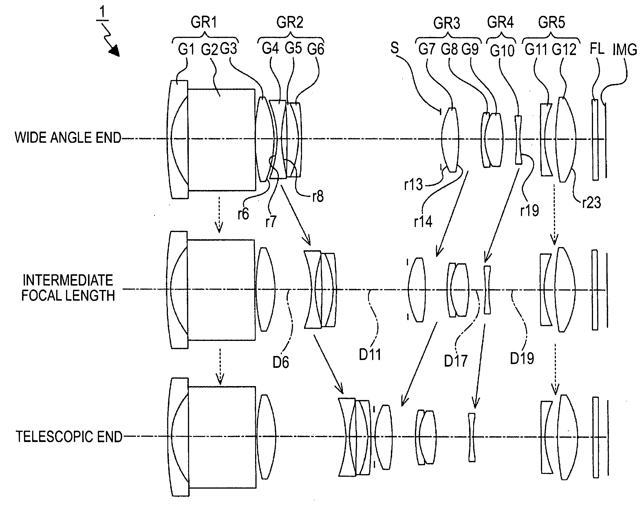
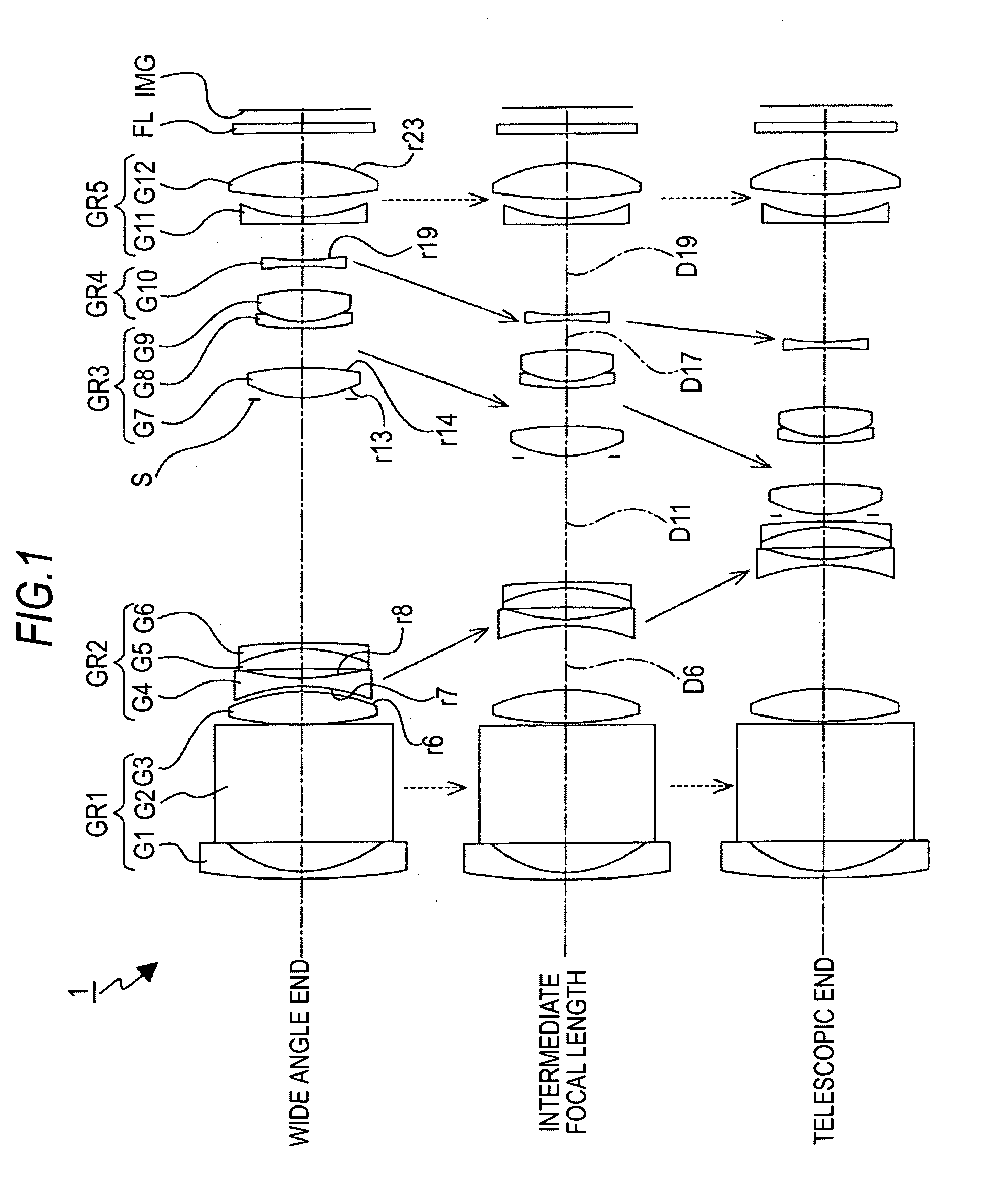
[0156]FIG. 1 shows the lens configuration of a zoom lens 1 in First Example of the invention.

[0157]The zoom lens 1 includes a first lens group GR1 having positive refracting power, a second lens group GR2 having negative refracting power, a third lens group GR3 having positive refracting power, a fourth lens group GR4 having negative refracting power, and a fifth lens group GR5 having positive refracting power arranged in this order from the object side toward the image side.

[0158]The zoom lens 1 has a variable power ratio of 5.5.

[0159]The first lens group GR1 is formed of a negative meniscus lens G1 with a convex surface facing the object side, a rectangular prism G2 used as a reflection member for deflecting the optical path by 90 degrees, and a positive biconvex lens G3 arranged in this order from the object side toward the image side.

[0160]The second lens group GR2 is formed of a negative biconcave lens G4 and a doublet obtained by bonding a positive meniscus lens G5 with a conv...

second example

[0175]FIG. 5 shows the lens configuration of a zoom lens 2 in Second Example of the invention.

[0176]The zoom lens 2 includes a first lens group GR1 having positive refracting power, a second lens group GR2 having negative refracting power, a third lens group GR3 having positive refracting power, a fourth lens group GR4 having negative refracting power, and a fifth lens group GR5 having positive refracting power arranged in this order from the object side toward the image side.

[0177]The zoom lens 2 has a variable power ratio of 6.4.

[0178]The first lens group GR1 is formed of a negative meniscus lens G1 with a convex surface facing the object side, a rectangular prism G2 used as a reflection member for deflecting the optical path by 90 degrees, and a positive biconvex lens G3 arranged in this order from the object side toward the image side.

[0179]The second lens group GR2 is formed of a negative biconcave lens G4, a positive biconvex lens G5, and a negative meniscus lens G6 with a con...

third example

[0193]FIG. 9 shows the lens configuration of a zoom lens 3 in Third Example of the invention.

[0194]The zoom lens 3 includes a first lens group GR1 having positive refracting power, a second lens group GR2 having negative refracting power, a third lens group GR3 having positive refracting power, a fourth lens group GR4 having positive refracting power, a fifth lens group GR5 having negative refracting power, and a sixth lens group GR6 having positive refracting power arranged in this order from the object side toward the image side.

[0195]The zoom lens 3 has a variable power ratio of 5.5.

[0196]The first lens group GR1 is formed of a negative meniscus lens. G1 with a convex surface facing the object side, a rectangular prism G2 used as a reflection member for deflecting the optical path by 90 degrees, and a positive biconvex lens G3 arranged in this order from the object side toward the image side.

[0197]The second lens group GR2 is formed of a negative biconcave lens G4, a positive men...


PUM


Abstract

A zoom lens includes: a first lens group including a reflection member that deflects an optical path by 90 degrees and having positive refracting power; a second lens group having negative refracting power; a third lens group having positive refracting power; at least one lens group having negative refracting power and at least one lens group having positive refracting power disposed as a fourth lens group and the following lens groups, the first to third lens groups and the fourth and following lens groups arranged in this order from an object side toward an image side; and an aperture diaphragm disposed in the vicinity of the third lens group, wherein in zooming from a wide angle end state to a telescopic end state, the first lens group is fixed, the second lens group is moved toward the image side, and the fourth lens group is moved toward the object side, and the zoom lens satisfies the following conditional equation1<(R1B+R21A) / (R1B−R21A)<20.

Description

BACKGROUND OF THE INVENTION[0001]1. Field of the Invention[0002]The present invention relates to a zoom lens and an imaging apparatus, and particularly to a technical field of a zoom lens and an imaging apparatus preferably used in a digital video camcorder, a digital still camera, and other electronic cameras and characterized by a compact size, a high variable power ratio, and high performance.[0003]2. Description of the Related Art[0004]In recent years, a digital video camcorder, a digital still camera, and other similar apparatus using a CCD (Charge Coupled Device), a CMOS (Complementary Metal-Oxide Semiconductor) device, or any other solid-state imaging device have rapidly come into wide use. As such digital cameras and other similar apparatus have come into wide use, there is a strong demand particularly on wide-angle, high variable power ratio zoom lenses suitable for a large number of pixels. There is also a strong demand on size reduction, in particular, thickness reduction...

Claims


Application Information

Patent Timeline
Patent Type & Authority Applications(United States)
IPC IPC(8): G02B15/14H04N5/232
CPCG02B15/173G02B15/145121G02B15/1461
Inventor KANETAKA, FUMIKAZU
Owner SONY CORP
Why Eureka
Try Eureka