
Dimmer Adaptable to Either Two or Three Active Wires

a technology of dimmer and active wire, which is applied in the direction of electric variable regulation, process and machine control, instruments, etc., can solve the problems of limiting the maximum load resistance that can be connected, limiting the maximum lighting level of light load, and exacerbated problems

Active Publication Date: 2011-08-11
CRESTRON ELECTRONICS
View PDF38 Cites 52 Cited by
  • Summary
  • Abstract
  • Description
  • Claims
  • Application Information

AI Technical Summary

Benefits of technology

[0019]When used in a dimmer with screw terminals this is particularly important as it eliminates the need for a jumper wire to reconnect the neutral terminal to the lighting load

Problems solved by technology

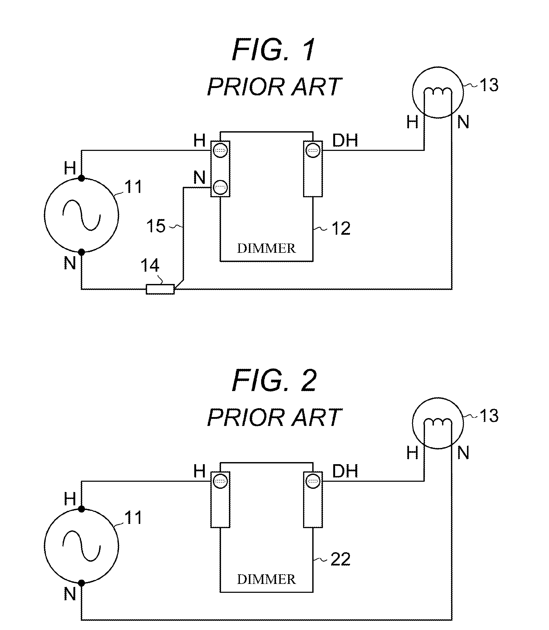
This limits the maximum lighting level of light load 13 and also limits the maximum load resistance that can be connected.
This problem is exacerbated for two-wire dimmers that require additional current draw, such as those containing radio transceivers.
One of the specific problems in the field is that installers would like the choice of wiring dimmers in either the two-wire or three-wire configurations, as described above, but are desirous of only stocking one standard type dimmer to avoid the cost and complexity associated with stocking different part numbers.
This is necessary especially for magnetic load types, such as low voltage transformers, because charging up asymmetrically can lead to heating in the transformer coil which can damage the transformer.
Charging asymmetrically also limits the ability for the manually configurable dimmer 32 internal power supply to charge fully.
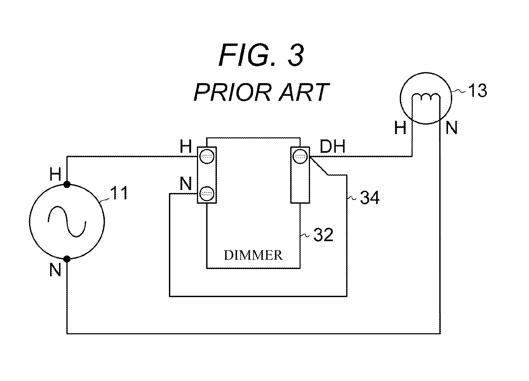
The external jumper 34 would still be needed to configure the manually configurable dimmer 32 into a two-wire configuration as in the equivalent dimmer with flying leads but when screw terminals are introduced, this external jumper 34 jumper is likely to be ignored or misapplied by the installer resulting in faulty operation or failure of the device.

Method used


Image

  • Dimmer Adaptable to Either Two or Three Active Wires
  • Dimmer Adaptable to Either Two or Three Active Wires
  • Dimmer Adaptable to Either Two or Three Active Wires

Examples


Embodiment Construction

[0080]The present invention is designed to allow residential electrical contractors to use a single type lighting dimmer for both two-wire and three-wire applications.

MODE(S) FOR CARRYING OUT THE INVENTION

[0081]As described previously, present practice provides for a manually configurable dimmer for which the installer either adds an external jumper wire for two-wire applications or deletes this jumper wire for three-wire applications. There is no provision for retaining the external jumper if it is not required and if the jumper is installed incorrectly, serious equipment damage may occur.

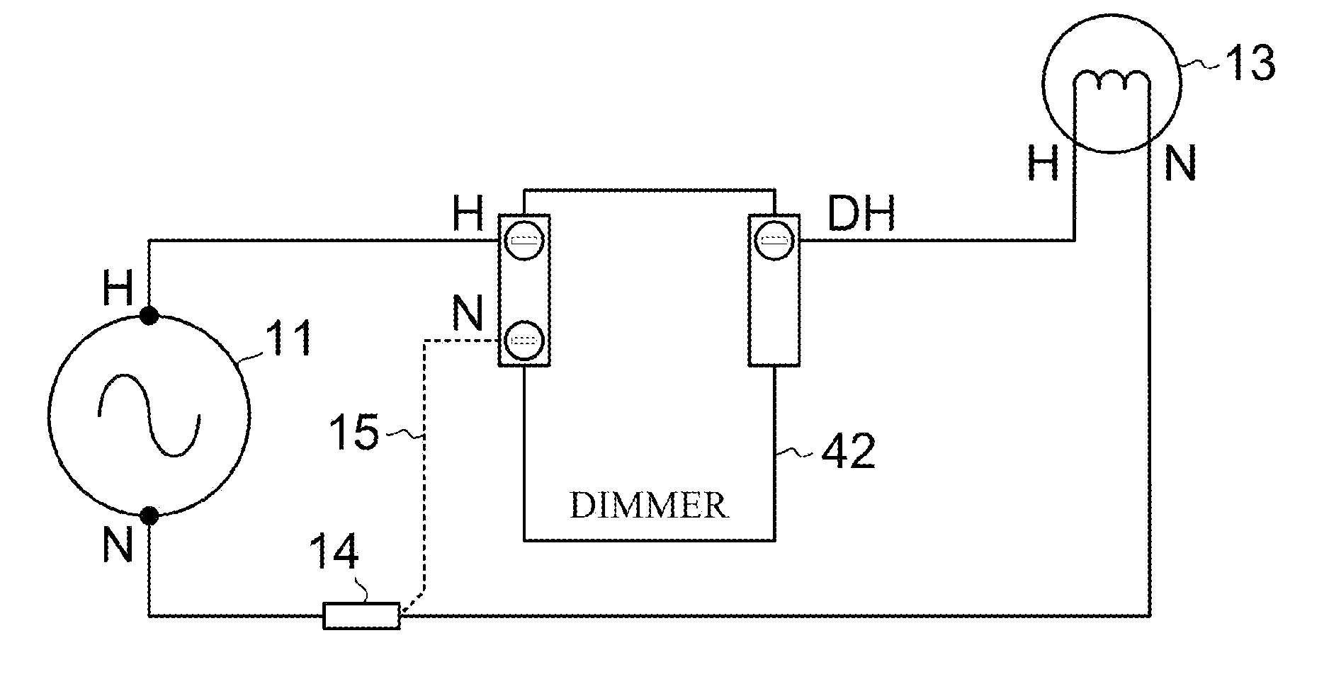
[0082]Now, refer to FIG. 4 which shows a standard dimmer 42, which is adaptable to either two or three active wires in accordance with the present invention. The standard dimmer 42 is operated in the two-wire configuration by connecting the AC source 11 hot (H) wire to the standard dimmer 42 hot (H) and the lighting load 13 hot (H) wire to the standard dimmer 42 dimmer hot (DH).

[0083]The standard ...


PUM


Abstract

A dimmer adaptable to either two (H, DH) or three (H, N, DH) active wires includes a first full-wave rectifier (D1, D2, D3, D4) across an AC power hot (H) terminal and a dimmer hot (DH) terminal and a second full-wave rectifier (D1, D4, D5, D6) across the AC power hot (H) terminal and an AC power neutral (N) terminal. The dimmer operates in a two-wire configuration by drawing power through a load when a control circuit is not conducting or in a three-wire configuration, when the AC power neutral (N) terminal is connected, by drawing power from AC power hot (H) and AC power neutral (N) terminals. The dimmer operates according to a first set of preset dim levels when current is flowing through the first rectifier and according to a second set of preset dim levels when current is flowing through the second rectifier.

Description

BACKGROUND OF THE INVENTION[0001]1. Technical Field[0002]The present invention relates to a load control device and more specifically to a lighting dimmer that is operable when connected to either two or three active electrical wires.[0003]2. Background Art[0004]It is known to those skilled in the art, that standard 120 VAC residential wiring provides three conductors (e.g. wires) to which an installer can attach various equipment, such as lighting dimmers. It is also known that two of these three conductors are active current carrying conductors, meaning that connections to these active conductors are required to complete a functional circuit. The US National Electrical Code specifies, for 120 VAC residential wiring, that a first active conductor with significant voltage to earth ground be identified as a ‘hot’ (H) conductor and color-coded black and that a second active conductor near ground potential be identified as a ‘neutral’ (N) conductor and color-coded white. US National El...

Claims


Application Information

Patent Timeline
IPC IPC(8): H05B41/16
CPCH05B39/044Y02B20/146H05B39/08Y02B20/00
Inventor KUMAR, RUSSIKESH
Owner CRESTRON ELECTRONICS
Learn More