
Pipe lighter

a lighter and pipe technology, applied in the field of lighters, can solve the problems of inconvenience for people who smoke, inability to direct aim the flame at the smoking substance, and inability to carry the smoking substance, so as to enhance the practice of inhaler. the effect of us

Inactive Publication Date: 2011-08-11
BAO FAN
View PDF1 Cites 3 Cited by
  • Summary
  • Abstract
  • Description
  • Claims
  • Application Information

AI Technical Summary

Benefits of technology

[0009]An object of the present invention is to provide a pipe lighter, which comprises a lighter apparatus equipped with an inhaler apparatus to form a single portable apparatus for enhancing the practice use of the inhaler apparatus.

Problems solved by technology

Accordingly, how to carry the smoking substance is another issue.
Therefore, the smokers must need to bring a lot of smoking tools at the same time and this causes inconvenience for people who smoke.
Even though the smoker may have the lighter and the pipe on hand, it is not guaranteed that the user can be able to directly aim the flame at the smoking substance.
In other words, it is not easy for people to ignite the tobacco in outdoor environment, especially in a windy condition.
Moreover, cleaning the pipe after smoking is a big issue for maximizing and extending the life span of the pipe.
However, for some small pipes or long channel pipes, it is hard for people to clean the ash and the last bits out by using a pipe tool.
If the unburned tobacco and the ash doesn't come out during last clean, the flavor of the cigarette or the tobacco dramatically ruined by the residue element.
The size of the pipe and the tool for cleaning pipe are usually bulky, and hard for people to carry them on hand.
Also, when burning smoking substance in the combustion chamber of the pipe, an uneven burning is resulted owing to failure to provide an efficient ignition or burning mechanism.
The smoking substance on the uppermost layer or in the centre area of the combustion chamber may easily get burnt while the smoking substance beneath the uppermost layer or in the peripheral area of the combustion chamber may be wasted without being burnt.

Method used


Image

  • Pipe lighter
  • Pipe lighter
  • Pipe lighter

Examples


Embodiment Construction

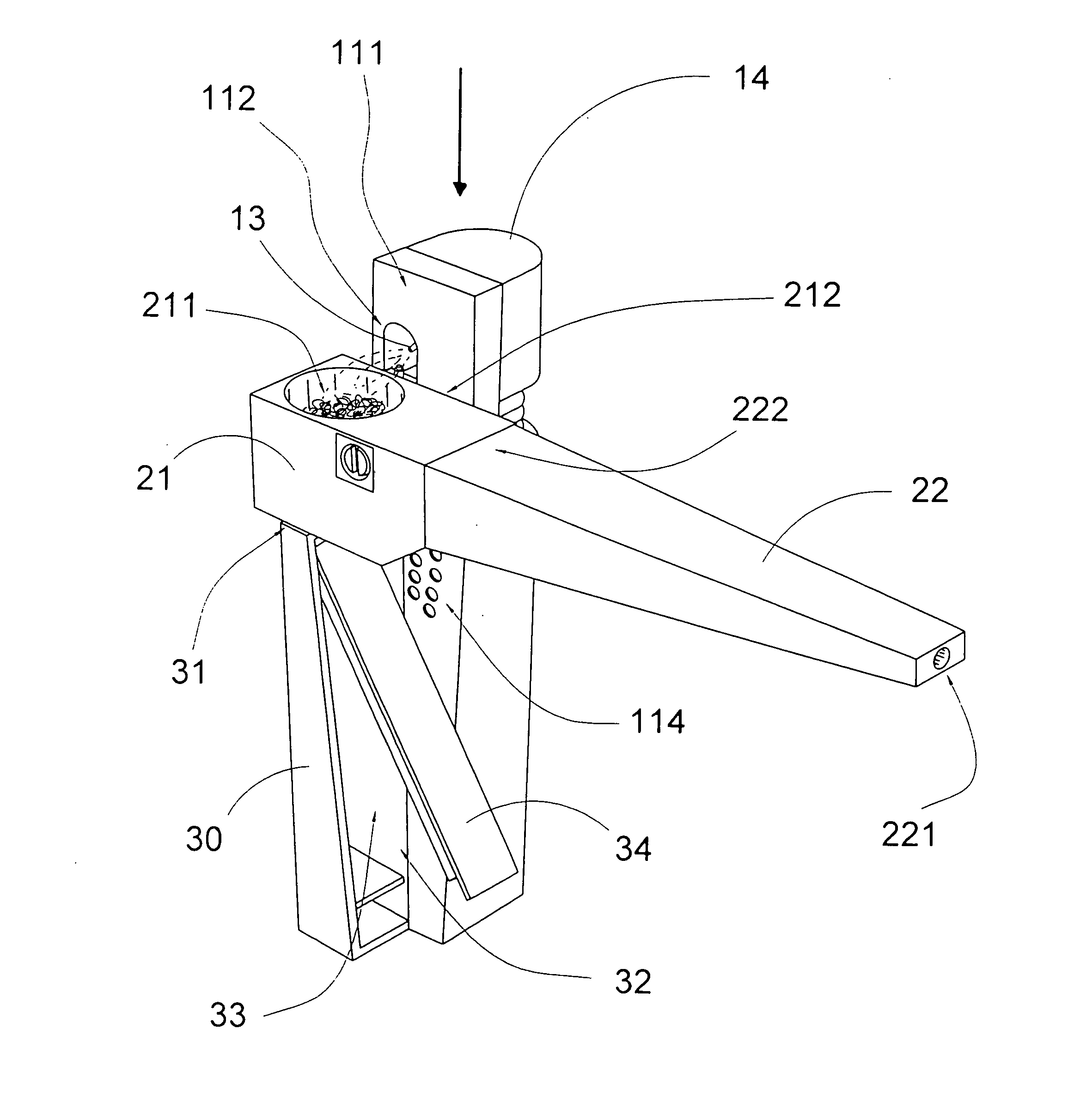
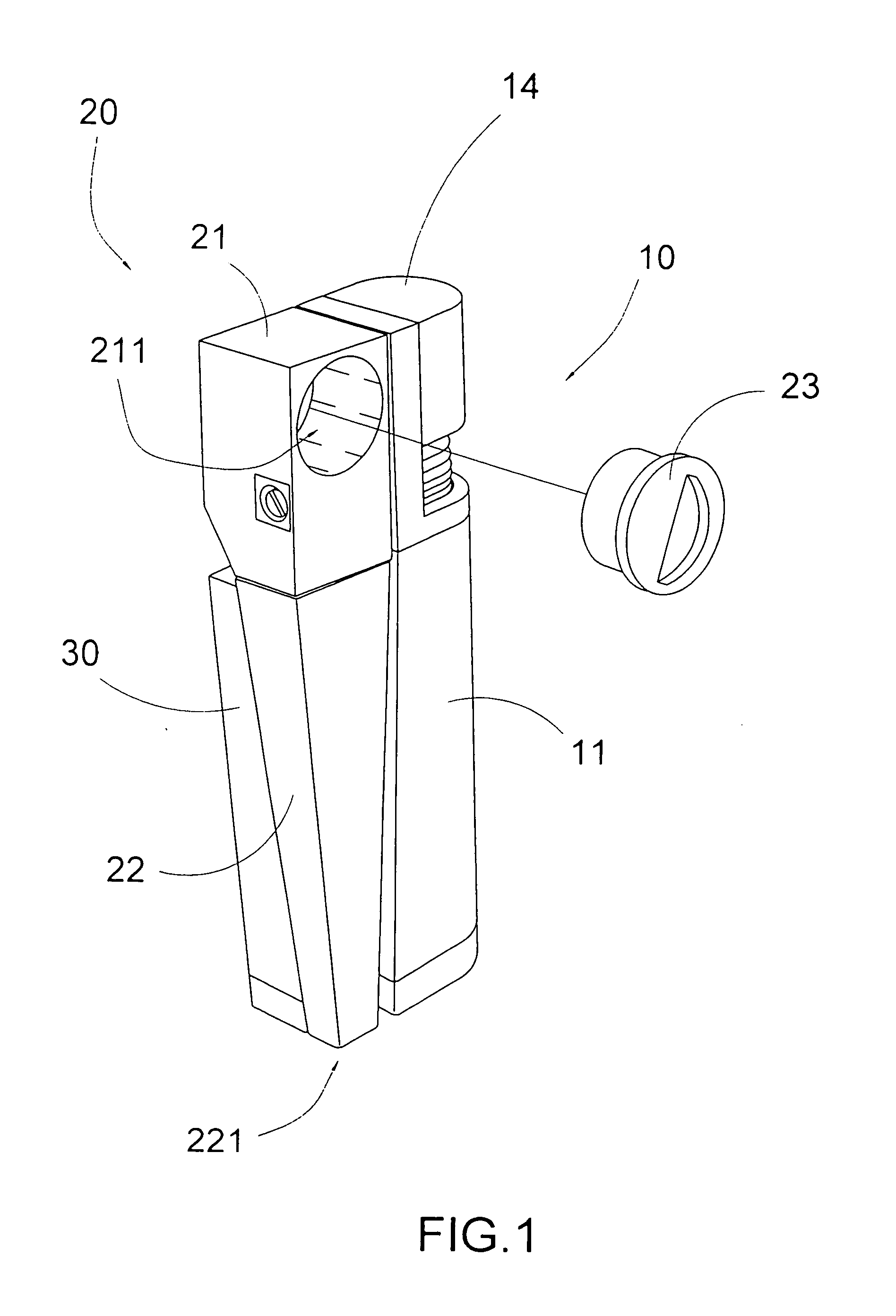
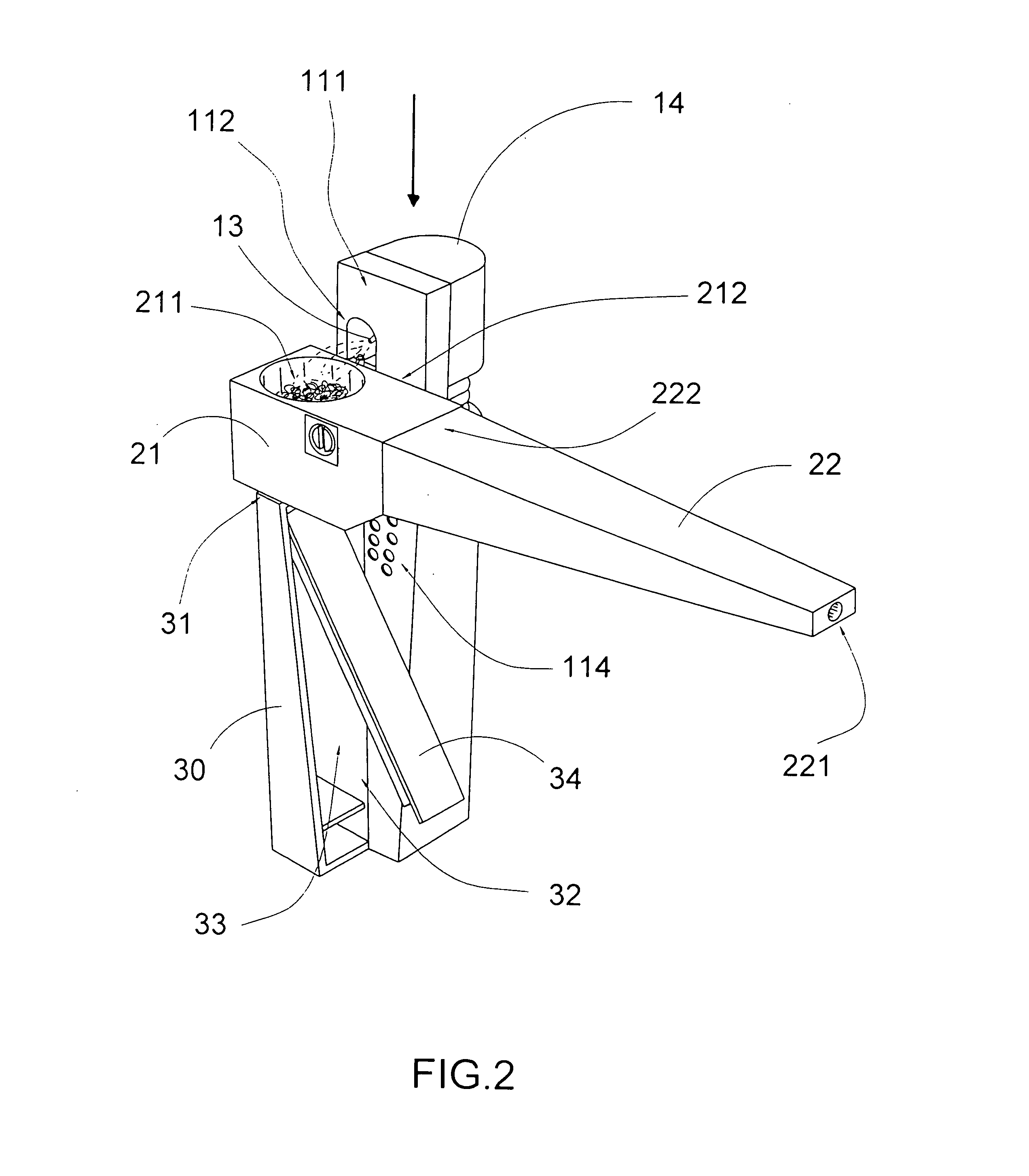
[0047]Referring to FIGS. 1 to 2 of the drawings, a pipe lighter according to a preferred embodiment of the present invention is illustrated, wherein the pipe lighter comprises a lighter apparatus 10 and an inhaler apparatus 20 coupling with the lighter apparatus 10.

[0048]The lighter apparatus 10 comprises a lighter housing 11 having a housing sidewall 111, a flame opening 112 provided at the housing sidewall 111, and a fuel storage chamber 113 for storing liquefied gas therewithin.

[0049]The lighter apparatus 10 further comprises an ignition unit 12 supported within the lighter housing 11, a flame nozzle 13 operatively extended from the fuel storage chamber 113 to the flame opening 112 for releasing the gas in a controllable manner, and an actuator 14 which is movably supported on the lighter housing 11 and is arranged in such a manner that when the actuator 14 is depressed, the gas in the fuel storage chamber 113 is released towards the flame nozzle 13 while the ignition unit 12 is ...


PUM


Abstract

A pipe lighter includes a lighter apparatus coupling with an inhaler apparatus. The inhaler apparatus includes a crucible unit coupled with the housing sidewall of the lighter housing and a tubular inhaling guider extended from the crucible unit, wherein the crucible unit has a substance chamber positioned adjacent to a flame opening of the lighter apparatus for retaining a smoking substance in the substance chamber, and a burner unit which is sized to fittingly and complimentarily engaging with the crucible unit to cover and evenly distribute the heat inside the substance chamber, thereby the smoking is evenly burnt which is then guided to flow towards the tubular inhaling guider. The pipe lighter is compact in size which substantively the same size as a disposable lighter, and is convenience to carry and use.

Description

CROSS REFERENCE OF RELATED APPLICATION[0001]This is a Continuation-In-Parts application that claims the benefit of priority under 35 U.S.C. §119 to a non-provisional application Ser. No. 12 / 291,809, filed Nov. 12, 2008.BACKGROUND OF THE PRESENT INVENTION[0002]1. Field of Invention[0003]The present invention relates to a lighter, and more particularly to a pipe lighter which comprises a lighter apparatus equipped with an inhaler apparatus to form a single portable apparatus for enhancing the practice use of the inhaler apparatus.[0004]2. Description of Related Arts[0005]A pipe is a common tool for tobacco smoking and typically consists of a small chamber for the combustion of tobacco. Generally, the pipe is commonly made of briar, corncob, meerschaum, and clay. People who want smoking usually carry a lighter to ignite the tobacco inside the pipe. However, no matter which type of pipe is, the smokers must carry the lighter or other lighting tool in order to ignite the tobacco. Accordi...

Claims


Application Information

Patent Timeline
Patent Type & Authority Applications(United States)
IPC IPC(8): A24F3/00
CPCA24F3/00
Inventor BAO, FAN
Owner BAO FAN
Learn More