
Power line communication system and method

a power line communication and power line technology, applied in the field of communication systems, can solve the problems of inability to communicate with the outside world, inability to add an aftermarket accessory, for example, a rear seat dvd player, and a large amount of wiring, so as to reduce electrical nois

Active Publication Date: 2011-08-04
PANASONIC AUTOMOTIVE SYST OF AMERICA
View PDF21 Cites 22 Cited by
  • Summary
  • Abstract
  • Description
  • Claims
  • Application Information

AI Technical Summary

Benefits of technology

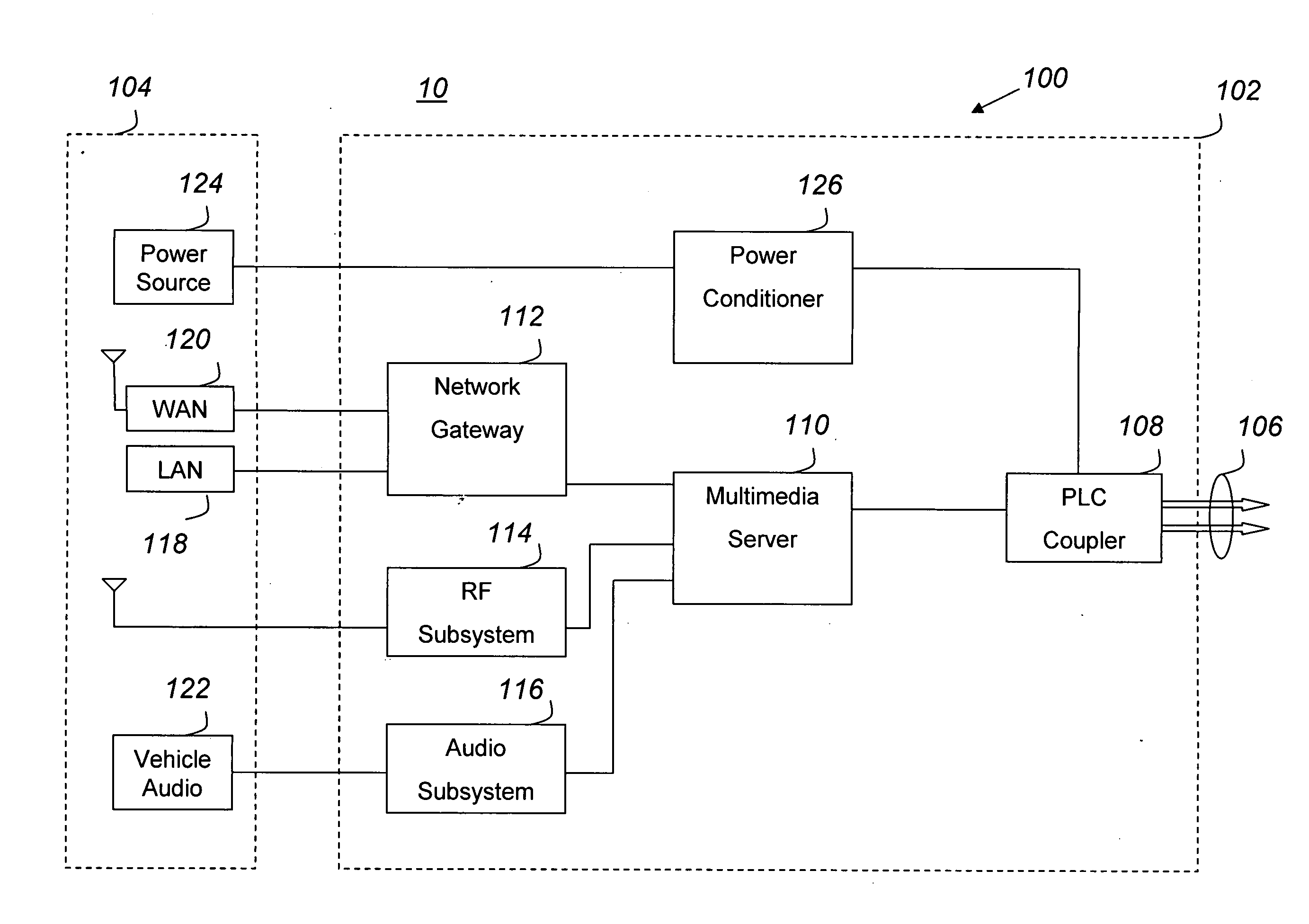
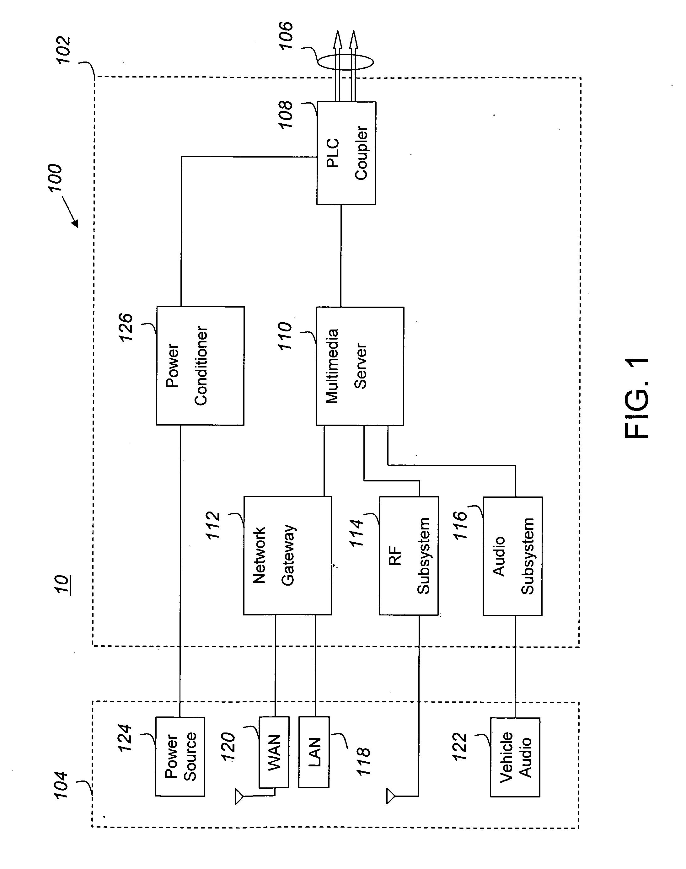
[0005]In some exemplary embodiments, the PLC server includes a power conditioner that reduces electrical noise on the PLC bus, thereby eliminating the use of individual power conditioners for each device coupled to the PLC bus. The PLC server may also include a PLC coupler that includes a first communications port coupled to the PLC bus and a second communications port coupled to a multimedia server.

Problems solved by technology

However, the connectivity of these various media systems is usually somewhat limited.
In other words, most of these media systems are not integrated with one other, and some media systems may not be able to communicate with the outside world.
Furthermore, the addition of an aftermarket accessory, for example, a rear-seat DVD player, would likely involve an expensive rewiring process to link the DVD player into the vehicular power and communication system.

Method used


Image

  • Power line communication system and method
  • Power line communication system and method
  • Power line communication system and method

Examples


Embodiment Construction

[0018]One or more specific embodiments of the present invention will be described below. In an effort to provide a concise description of these embodiments, not all features of an actual implementation are described in the specification. It should be appreciated that in the development of any such actual implementation, as in any engineering or design project, numerous implementation-specific decisions may be made to achieve the developers' specific goals, such as compliance with system-related and business-related constraints, which may vary from one implementation to another. Moreover, it should be appreciated that such a development effort might be complex and time consuming, but would nevertheless be a routine undertaking of design, fabrication, and manufacture for those of ordinary skill having the benefit of this disclosure.

[0019]Exemplary embodiments of the present invention relate to a power line communication (PLC) system for use in a vehicle. The PLC system may provide a u...


PUM


Abstract

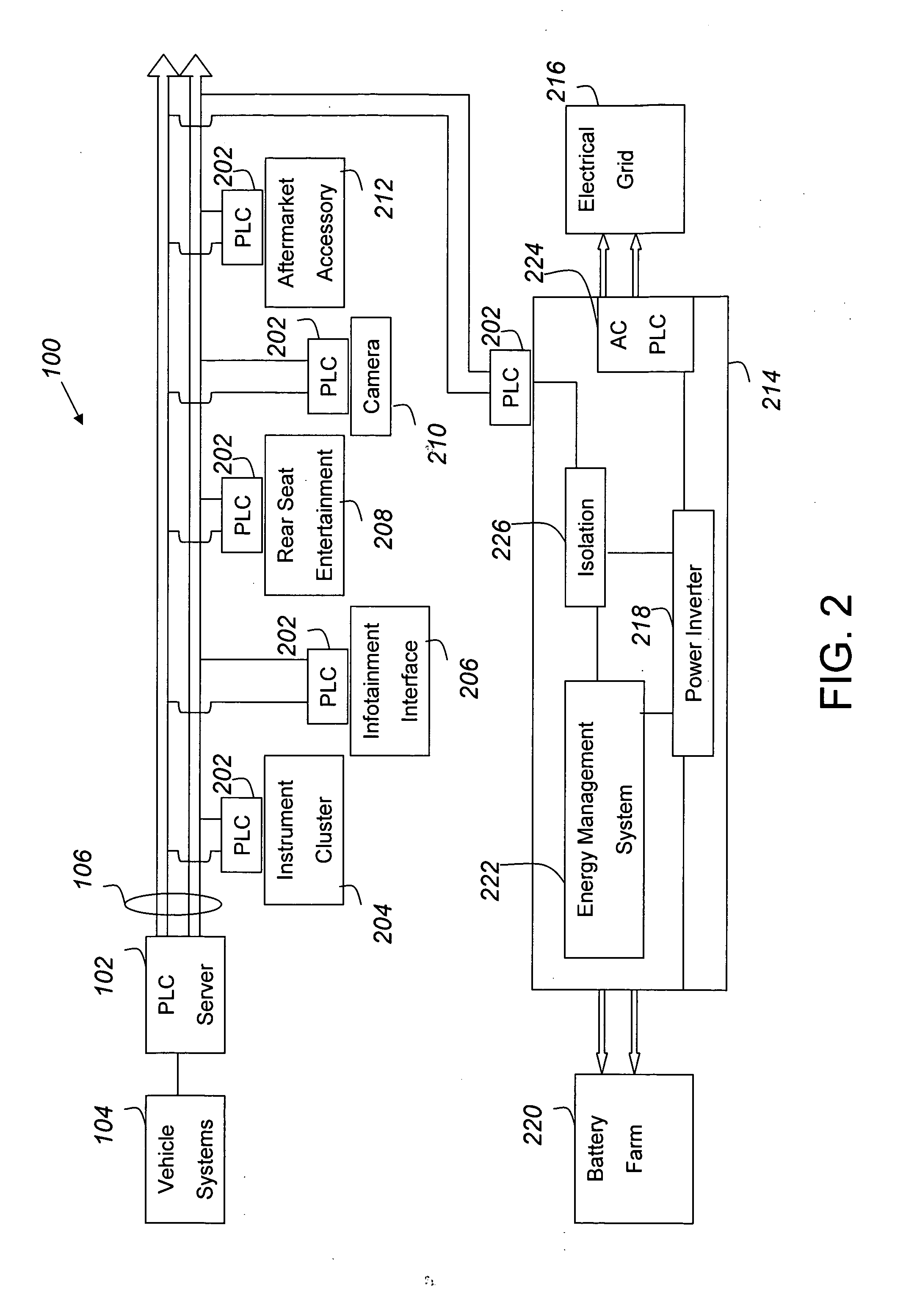
Exemplary embodiments of the present invention relate to a power line communication (PLC) system. For example, the PLC system may include a PLC server configured to provide electrical power and electronic communications through a PLC bus to a number of electronic devices, such as an instrument cluster, infotainment interface, rear-seat entertainment console, aftermarket accessories, and the like. The PLC system may also include a power system that may be coupled to an electrical grid for charging a battery associated with one or more of the electronic devices. The power system may be communicatively coupled to the PLC bus, enabling the devices coupled to the PLC bus to communicate with a service provider through the electrical grid. The communications between the devices coupled to the PLC bus and remote devices coupled through the electrical grid may be conducted using a common communication protocol.

Description

FIELD OF THE INVENTION[0001]The present invention generally relates to a communication system. More specifically, the present invention relates to a power line communication (PLC) system for a vehicle. In some embodiments, the PLC system can optionally be linked with a service provider through an electrical grid that provides power and electronic communications.BACKGROUND OF THE INVENTION[0002]This section is intended to introduce the reader to various aspects of art which may be related to various aspects of the present invention which are described and / or claimed below. This discussion is believed to be helpful in providing the reader with background information to facilitate a better understanding of the various aspects of the present invention. Accordingly, it should be understood that these statements are to be read in this light, and not as admissions of prior art.[0003]Vehicles, such as cars, trucks, SUVs, minivans, and boats, among others, typically include various media sys...

Claims


Application Information

Patent Timeline
IPC IPC(8): B60L11/00G06F17/00G01C21/00G06F3/048G06F1/26G05B11/01
CPCB60L11/1838Y02T90/121B60L11/1848H04B3/542H04B2203/545H04B2203/5458H04B2203/547Y02T10/7005Y02T90/128Y02T90/14Y02T90/16Y02T90/163Y02T90/169Y04S30/14H04B3/54B60L11/1846B60L1/003B60L1/02B60L3/12B60L2200/32B60L2200/36B60L2210/30B60L2210/40B60L2240/12B60L2240/34B60L2240/441B60L2240/445B60L2240/622B60L2250/16B60L53/65B60L53/665B60L53/53B60L53/18Y02T10/7072Y02T10/72Y02T90/12Y02T90/167Y02T10/70
Inventor BURK, MICHAEL T.
Owner PANASONIC AUTOMOTIVE SYST OF AMERICA
Learn More