
Turbine engine component for adaptive cooling

a technology of adaptive cooling and turbine engine, which is applied in the direction of liquid fuel engines, marine propulsion, vessel construction, etc., can solve the problems of negative side effects on the overall performance of the compressor and/or the turbine section, material may still oxidise during operation, and the time of operation can be stretched further, and the downtime may be avoided. only marginal performance loss

Inactive Publication Date: 2011-08-04
SIEMENS AG
View PDF10 Cites 51 Cited by
  • Summary
  • Abstract
  • Description
  • Claims
  • Application Information

AI Technical Summary

Benefits of technology

[0010]The present invention seeks to find a solution in which the time of operation can be stretched further and downtime may be avoided even when oxidation of parts has already occurred, so that repair or replacement of parts can be performed at the next maintenance schedule and still providing a mode of operation with only marginal performance losses.
[0022]In contrast to provide a large number of cooling holes during manufacturing to accommodate the needs of worst case scenarios in regards of hot spots, the invention is advantageous because, if the heat will never reach an oxidising temperature, the depression will never become a cooling passage and therefore no performance losses will occur.

Problems solved by technology

Components such as gas turbine blades, vanes and others in a turbine or a combustion section of a gas turbine may be affected by hot fluids resulting in oxidation of the components.
Even though cooling may be necessary, the existence of cooling holes and the supply of cooling air to the region to be cooled—the cooling air may typically be taken from a compressor section of the gas turbine—may have negative side effects on the overall performance of the compressor and / or of the turbine section.
In installed gas turbines, even if thoroughly designed, material may still oxidise during operation, e.g. due to high temperature peaks.
To coat these passages may be difficult.

Method used


Image

  • Turbine engine component for adaptive cooling
  • Turbine engine component for adaptive cooling
  • Turbine engine component for adaptive cooling

Examples


Embodiment Construction

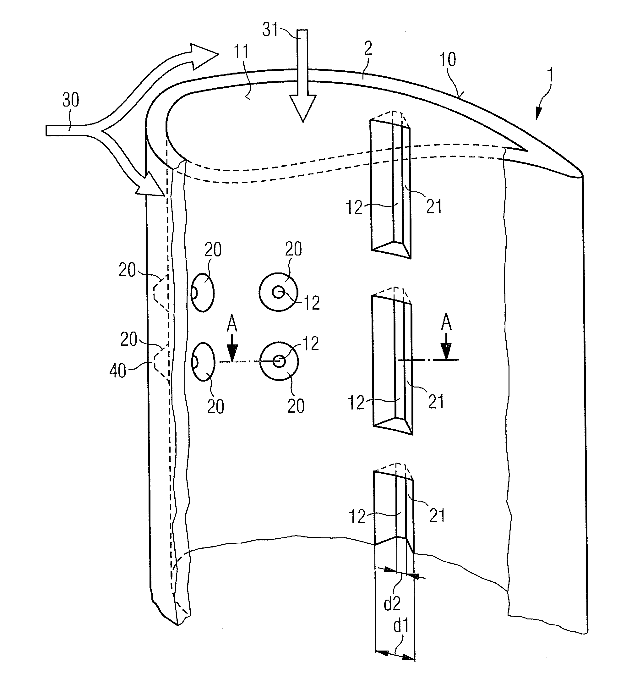
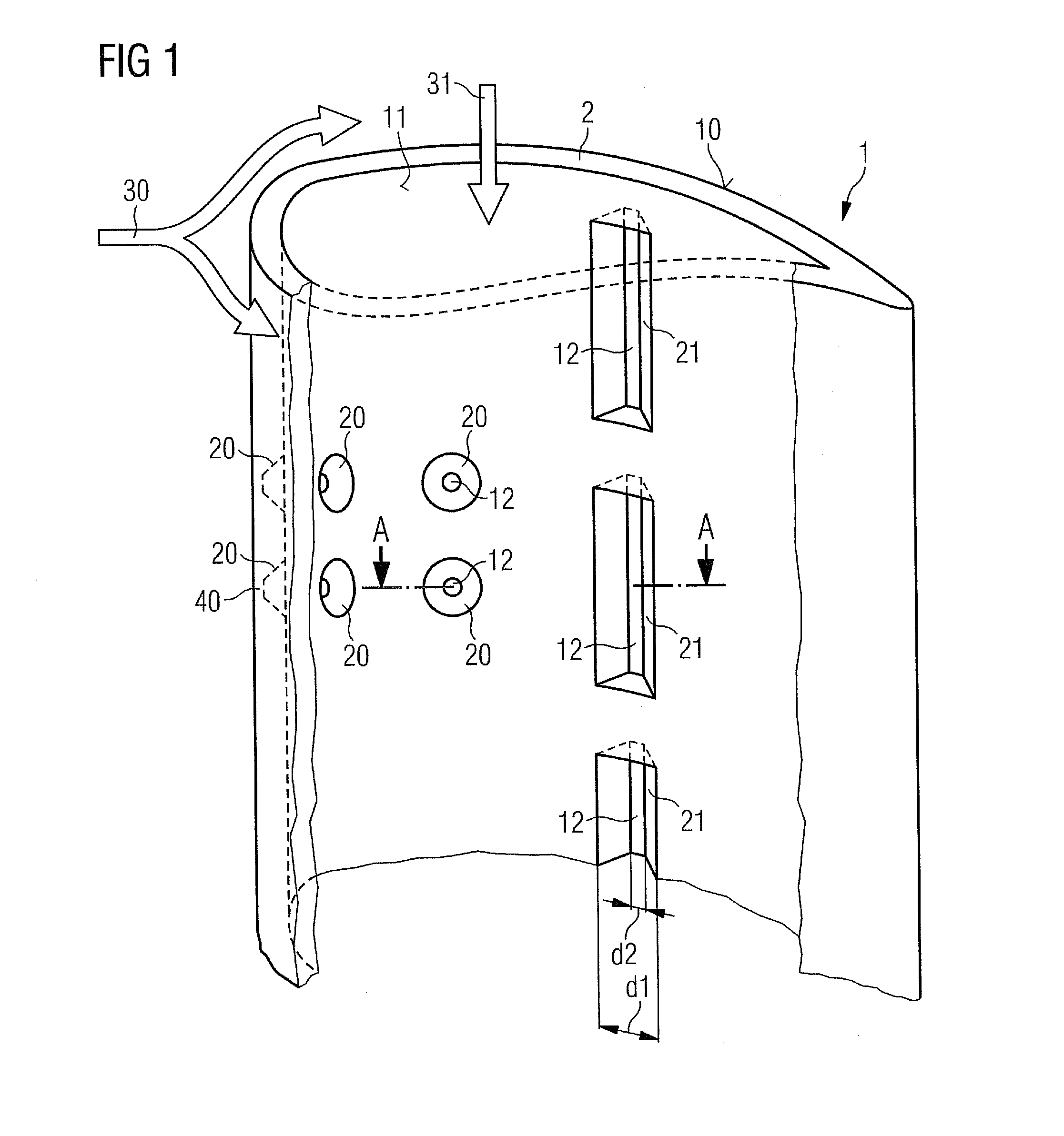
[0034]Referring now to FIG. 1, one half of an aerofoil 1 of a turbine is shown in a perspective view as seen from the inside of the aerofoil 1. The second half of the aerofoil 1 that would disallow the view to the inside of the aerofoil 1 is not shown is only indicated by broken and dashed lines.

[0035]The aerofoil 1, for example a guide vane or a blade within a turbine section of a gas turbine engine, represents the turbine engine component as defined in the invention and will be present in a working fluid flow 30 during operation. This working fluid flow 30 is indicated as a double arrow and may be a hot gas provided by a combustion chamber located upstream. The aerofoil 1 has a circumferential wall 2 as a body of turbine engine component and a cavity to allow cooling fluid—a cooling fluid flow 31 is indicated via a further arrow—to cool the wall 2 from the inside and to supply cooling holes (not shown in the figure).

[0036]The wall 2 has a first surface 10 which is exposed, in use,...


PUM


Abstract

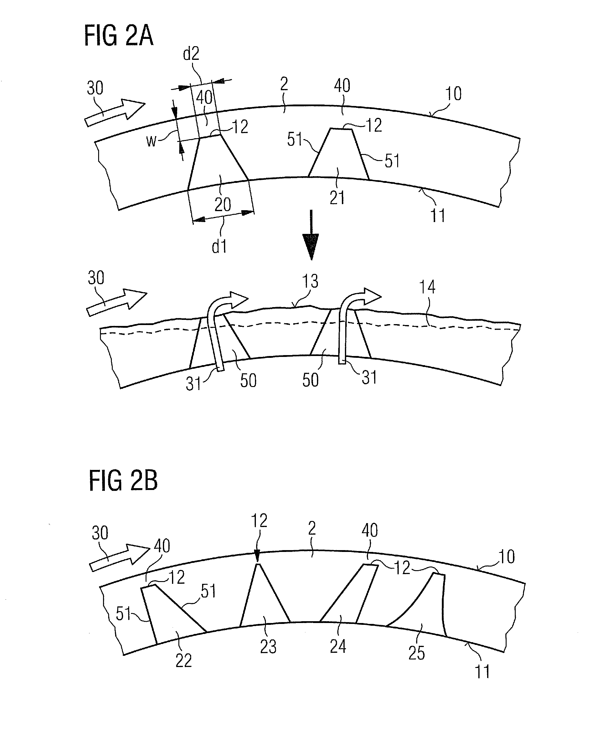
A turbine engine component, particularly an aerofoil, including a body is provided. The turbine engine component includes a first surface exposed to a working fluid of high temperatures during operation, a second surface including a depression, the depression is exposed to a cooling fluid during operation and oriented such that, starting from the second surface, the depression deepens in the direction of a back face of the first surface. Furthermore the body includes a body portion between the back face and the first surface. The depression is defined such that a diameter of the depression decreases from the second surface in direction of the back face.

Description

CROSS REFERENCE TO RELATED APPLICATIONS[0001]This application claims priority of European Patent Office application No. 1015248.8 EP filed Feb. 2, 2010, which is incorporated by reference herein in its entirety.FIELD OF THE INVENTION[0002]The invention relates to adaptive cooling of a hot turbine engine component, particularly a turbine aerofoil within a turbine section of a gas turbine engine.BACKGROUND OF THE INVENTION[0003]Components such as gas turbine blades, vanes and others in a turbine or a combustion section of a gas turbine may be affected by hot fluids resulting in oxidation of the components. This problem is addressed in several ways, e.g. by using heat resistant materials or by applying a coating, like a thermal barrier coating (TBC). Alternatively or additionally the components may be cooled. For this additional cooling, cooling air may be supplied and cooling features and cooling holes may be designed in regions to be cooled.[0004]Even though cooling may be necessary,...

Claims


Application Information

Patent Timeline
Patent Type & Authority Applications(United States)
IPC IPC(8): F01D5/18
CPCF01D5/186F01D5/187F01D5/288F05D2260/202F05D2270/11F05D2250/232F05D2250/292F05D2230/90
Inventor SHEPHERD, ANDREW
Owner SIEMENS AG
Learn More