
Multipath mitigation circuit for home network

a multi-path mitigation and home network technology, applied in the field of electronic filter assembly, can solve the problem of increasing the return loss of home network bandwidth

Active Publication Date: 2011-08-04
PPC BROADBAND INC
View PDF99 Cites 17 Cited by
  • Summary
  • Abstract
  • Description
  • Claims
  • Application Information

AI Technical Summary

Benefits of technology

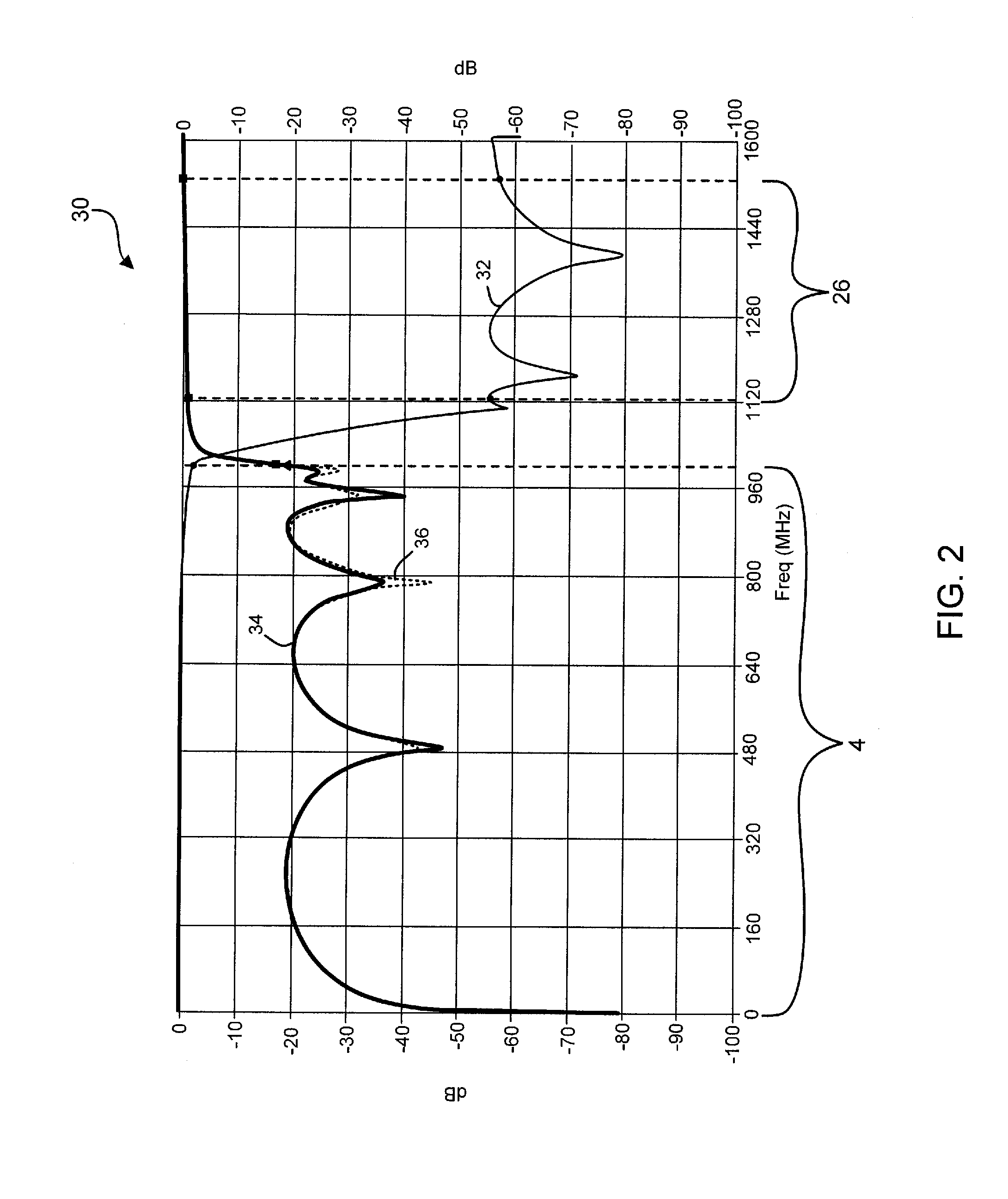
[0016]In another aspect of the invention, the frequency response of the circuit is further characterized by the return loss at the output and the input being more than 20 dB in the provider bandwidth and home network bandwidth.

Problems solved by technology

The multipath interference mitigation leg increases a return loss of the home network bandwidth.

Method used


Image

  • Multipath mitigation circuit for home network
  • Multipath mitigation circuit for home network
  • Multipath mitigation circuit for home network

Examples


Embodiment Construction

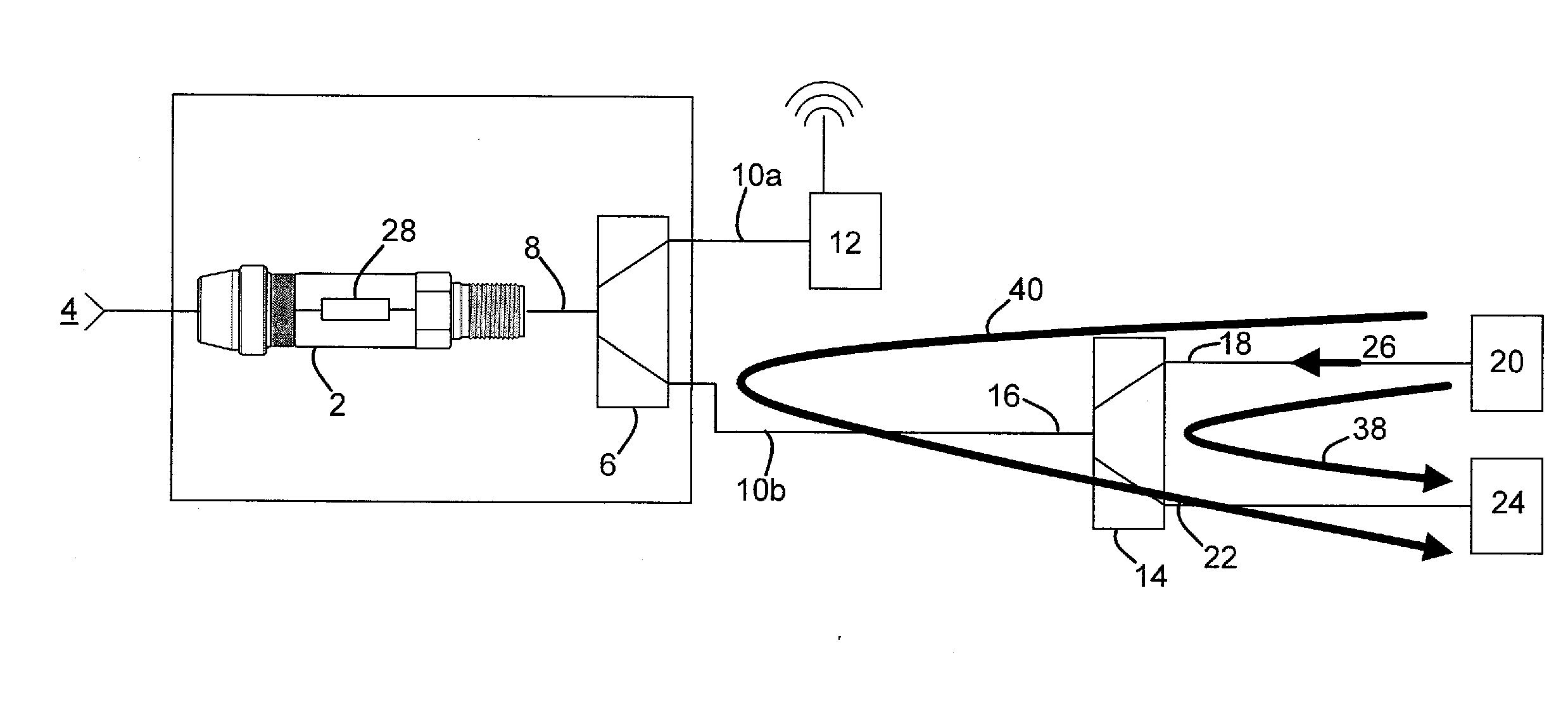
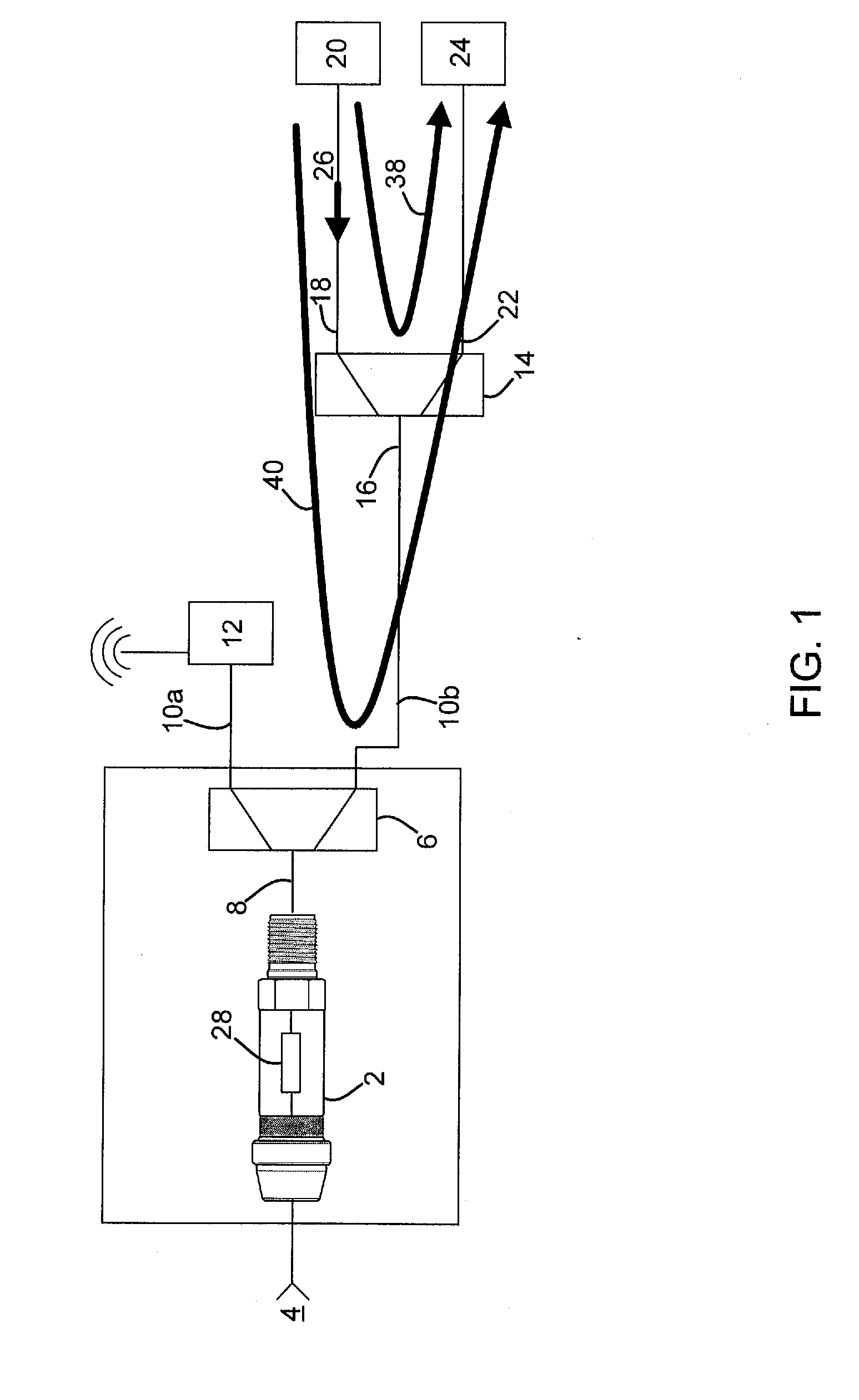
[0024]Referring to FIG. 1, a portion of an exemplary home network includes a filter housing 2 located at the point of entry to a premises. In the disclosed embodiment, the filter housing 2 is a standard female f-connector configured to pass a provider bandwidth 4, which may be a CATV system, for example. An exemplary CATV system typically includes a downstream component and an upstream component. The provider bandwidth 4 may propagate a downstream bandwidth in the 50-1,000 MHz range, and also carry an upstream bandwidth in the 7-49 MHz range.

[0025]The provider bandwidth 4 passes through a MoCA-enabled splitter 6 having an input port 8 and two distribution ports 10a, 10b respectively. In one example, distribution port 10a is coupled via coaxial cable to a MoCA-enabled device 12a such as a wireless router. Distribution port 10b is coupled to a second MoCA-enabled splitter 14. The second splitter 14 likewise includes an input port 16, a second distribution port 18 connected to a second...


PUM


Abstract

A filter circuit is provided having multipath interference mitigation. The filter includes a signal path extending from an input to an output. The signal path includes a conductive path and a ground. A pass band filter is disposed along the signal path between the input and the output. The pass band filter passes a first frequency spectrum in a provider bandwidth, and attenuates a second frequency spectrum in a home network bandwidth. The filter circuit further includes a multipath interference mitigation leg operatively branched from the signal path. The multipath interference mitigation leg increases a return loss of the home network bandwidth. A frequency response of the filter circuit is characterized by an insertion loss characteristic between the input and the output being less than 3 dB in the provider bandwidth, and more than 20 dB in the home network bandwidth. The frequency response is further characterized by a return loss characteristic at the output being more than 10 dB in the provider bandwidth and home network bandwidth.

Description

FIELD OF THE INVENTION[0001]The present invention relates generally to an electronic filter assembly for use in the cable television (CATV) industry, and more specifically to a circuit assembly that mitigates home data network signals from reflecting within a user's network.BACKGROUND OF THE INVENTION[0002]In many data distribution networks, electrical signals conveying information propagate along transmission lines across distances and through splitting devices. For example, in a cable television (CATV) network, media content propagates downstream from a head-end facility toward media devices located in various facilities such as homes and businesses. Along the way, the electrical signals conveying the media content propagate along main trunks, through taps, and along multiple branches that ultimately distribute the content to drop cables at respective facilities. The drop cable, which may be a single coaxial cable, typically is connected to a splitting device having two or more ou...

Claims


Application Information

Patent Timeline
Patent Type & Authority Applications(United States)
IPC IPC(8): H03H7/01
CPCH03H7/01H03H7/0138H03H7/1758H03H7/1766H03H7/06H03H7/0161H03H7/1741
Inventor ALKAN, ERDOGANPALINKAS, RAYMOND W.
Owner PPC BROADBAND INC
Learn More