
Coating layer removing apparatus and method for the same

a technology of coating layer and apparatus, which is applied in the direction of cell components, manufacturing tools, cell component details, etc., can solve the problems of limited lithium battery productivity, difficult to realize in practice, and difficult to increase the fabrication speed of such devices, so as to improve the damage rate of the substrate and promote the quality and yield of products.

Active Publication Date: 2011-08-04
PHOENIX BATTERY CORP
View PDF12 Cites 39 Cited by
  • Summary
  • Abstract
  • Description
  • Claims
  • Application Information

AI Technical Summary

Benefits of technology

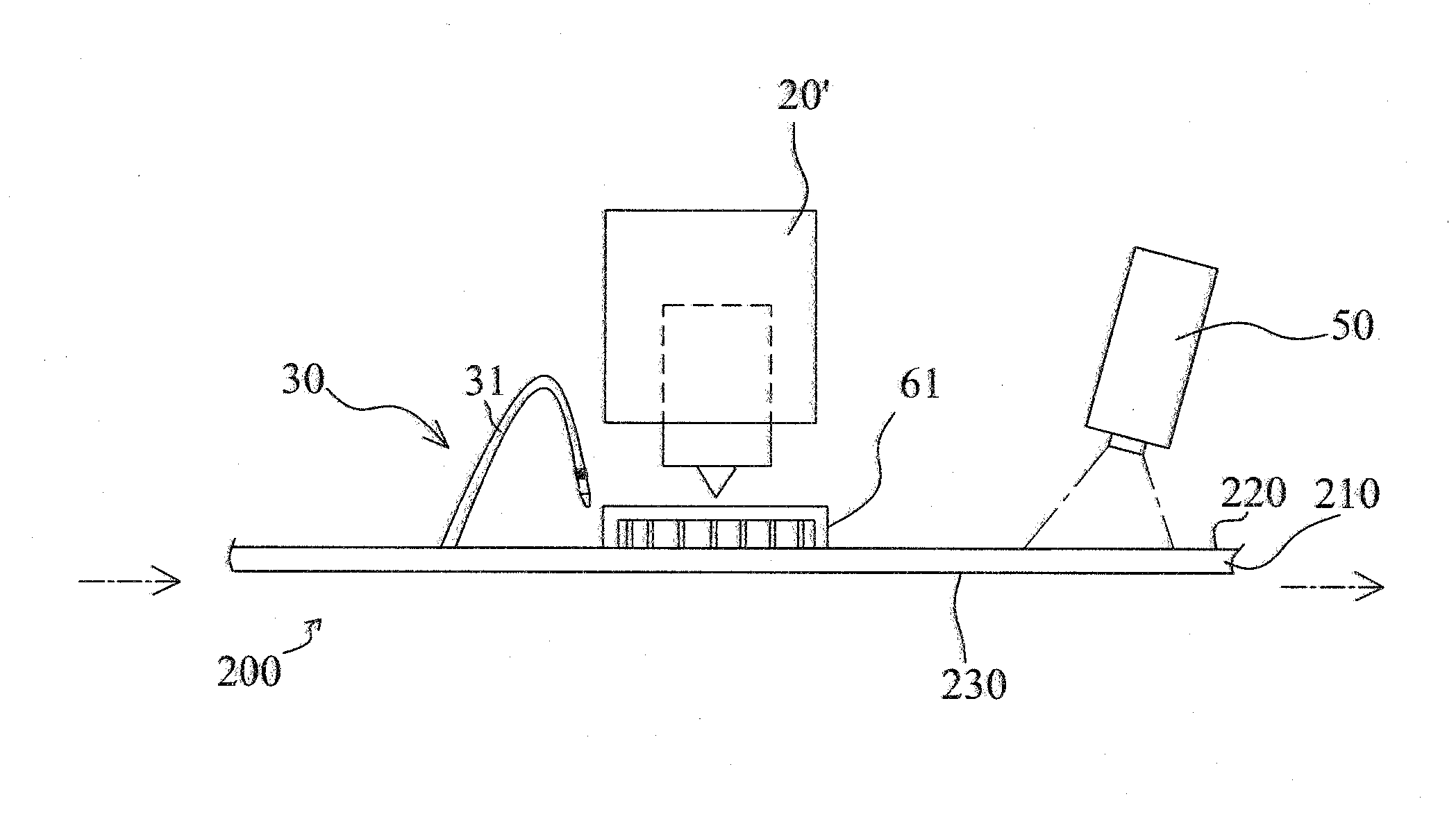
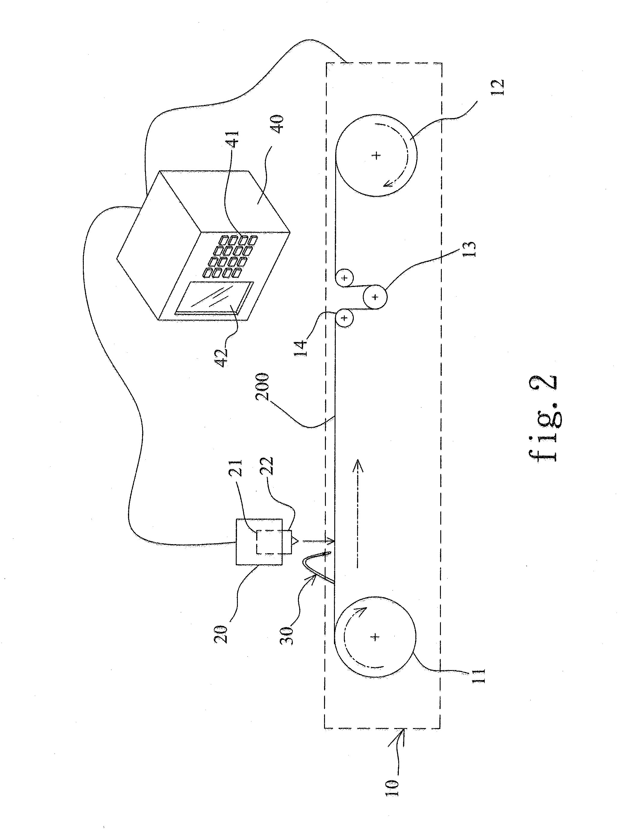
The present invention provides a coating layer removing apparatus and method using laser to remove coating layers on the surfaces of an electrode plate, improving the damage rate of the substrate and promoting the quality and yield of the products. The apparatus and method can form exposed areas on both the upper and lower surfaces of an electrode plate in a single cycle, favoring mass-production of lithium batteries, reducing fabrication cost, and promoting competitiveness of manufacturers. The apparatus includes a transport device, laser device, and control center, with the control center controlling the speed at which the transport device displaces the electrode plates, the timing at which the laser device emits laser beams, the count of the laser beams, and the penetration depths of the laser beams. The method includes setting the displacement speed and stop positions of the electrode plate into the control center, inputting the time interval between two laser beams, the count of the laser beams, and the penetration depths of the laser beams, and using the apparatus to automatically form the exposed areas on the surfaces of the electrode plate according to the input conditions.

Problems solved by technology

Although the lithium battery has a very large market share, the fabrication speed thereof is hard to increase.
The productivity of lithium batteries is limited by the fabrication of the electric-conduction tab and the electrode plate of the conventional electrode roll.
The abovementioned scheme is ideal in theory but hard to realize in practice.
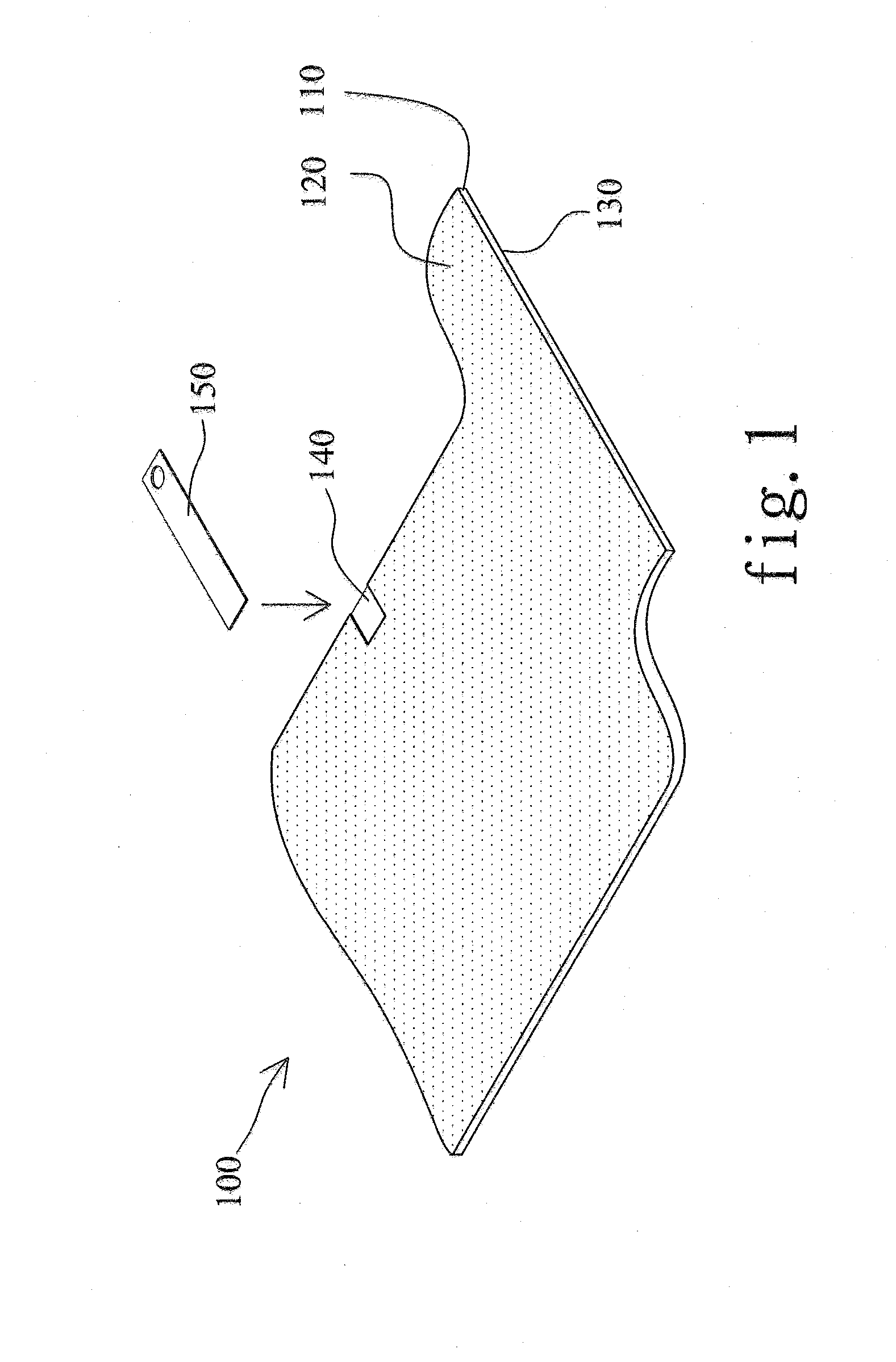
Because the electrode plate 100 is very thin, removing the coating layers 120 and 130 to expose the substrate 110 is usually undertaken manually, which is laborious and time-consuming.
Further, a slightly greater force applied by the worker may damage the very thin substrate 110.
In fact, either too great or too small a force applied by the worker would affect the quality and the discharging capability of the lithium battery.
However, the conventional technology can only remove a single coating layer 120 or 130 in one cycle.
Therefore, the manufacturers have to invest more manpower and capital to produce lithium batteries, which reduces the competitiveness of the Taiwan lithium battery manufacturers.
Thus, the damage rate of the electrode plates 100 is still high, and the yield and quality is still unstable, in the prior art.
Therefore, the competitiveness promoted by the prior art is limited.

Method used


Image

  • Coating layer removing apparatus and method for the same
  • Coating layer removing apparatus and method for the same
  • Coating layer removing apparatus and method for the same

Examples


Embodiment Construction

[0024]Refer to FIG. 2 and FIG. 3 a diagram and a block diagram respectively schematically showing a coating layer removing apparatus and the architecture thereof according to one embodiment of the present invention. The coating layer removing apparatus of the present invention comprises a transport device 10, a laser device 20, a blowing device 30 and a control center 40. The transport device 10 is used to displace a positive or negative electrode plate, which will be referred to as the electrode plate 200 thereinafter. The transport device 10 includes a releasing wheel unit 11, a winding wheel unit 12, a tension wheel unit 13 and two fixing wheel units 14. One end of the electrode plate 200 is fixed to the releasing wheel unit 11, and then inserted through the tension wheel unit 13 and the fixing wheel units 14, and finally fixed to the winding wheel unit 12. The releasing wheel unit 11 is a passive element, and the winding wheel unit 12 is an active element. When the winding wheel...


PUM

PropertyMeasurementUnit
areaaaaaaaaaaa
speedaaaaaaaaaa
coloraaaaaaaaaa

Abstract

The present invention discloses a coating layer removing apparatus and a method for the same. The apparatus of the present invention comprises a transport device displacing an electrode plate; a laser device having a laser head arranged above the displacement path of the electrode plate; and a control center electrically connected to the transport device and the laser device. The method of the present invention comprises mounting an electrode plate on the transport device; using the control center to set the speed of displacing the electrode plate, and program the time interval, count and penetration depths of the laser beams; and using the device of the present invention to form exposed areas equidistantly on the electrode plate. The apparatus of the present invention automatically removes a coating layer with a laser beam without directly contacting the electrode plate. Therefore, the present invention can fast form exposed areas of high quality.

Description

BACKGROUND OF THE INVENTION[0001]1. Field of the Invention[0002]The present invention relates to an apparatus to fabricate the electrode plate of a lithium battery, particularly to a coating layer removing apparatus and a method for the same, which can reduce the fabrication time and promote the yield rate.[0003]2. Description of the Related Art[0004]Lithium batteries have advantages of high energy density, compactness, environmental protection and combination ability. Therefore, lithium batteries have been widely used in many fields. With the increasing usage, more and more manufacturers invest in the technical development of lithium batteries.[0005]Although the lithium battery has a very large market share, the fabrication speed thereof is hard to increase. The productivity of lithium batteries is limited by the fabrication of the electric-conduction tab and the electrode plate of the conventional electrode roll. Refer to FIG. 1. The electrode plate 100 may be a positive or negati...

Claims


Application Information

Patent Timeline
Patent Type & Authority Applications(United States)
IPC IPC(8): B23K26/00H01M50/531
CPCY02E60/122B23K26/00Y02E60/10H01M50/531
Inventor CHUNG, I-FENG
Owner PHOENIX BATTERY CORP
Learn More