Control system for train doors and actuation method based on said system

a technology of control system and actuation method, which is applied in the direction of dc motor rotation control, field or armature current control, vehicle components, etc., can solve the problems of low reliability and electromechanical components, and achieve the effect of reducing the number of incidents

Inactive Publication Date: 2011-08-04
METRO DE MADRID
View PDF6 Cites 16 Cited by
  • Summary
  • Abstract
  • Description
  • Claims
  • Application Information

AI Technical Summary

Benefits of technology

[0013]The control system for controlling doors of the present invention thus solves the problems discussed above, minimizing the electromechanical elements used and therefore reducing the number of incidents.
[0015]In relation to the power control means of the motor, said means comprise a single bridge of four transistors capable of unifying the three stages that are typically performed independently, thus reducing the number of elements, which results in simplifying the assembly, reducing the number of breakdowns, etc.

Problems solved by technology

This high number of operations causes, on more occasions than desired, malfunctions due to different causes, especially due to the electromechanical nature of their components and therefore to their vulnerability to vibrations, dirt, etc.
These configurations present, however, as previously stated, the problem of using electromechanical components, such as relays, which offer low reliability.
On the other hand, in addition to the mentioned problems, it is necessary to consider the fact that in order to obtain information about the state and position of the doors, the solution typically adopted is that of using micro mechanical circuit breakers positioned along the travel, which has the drawbacks indicated above, and / or low-resolution encoders which give a very rough indication of the position of the door, not being valid for detecting small movements thereof.

Method used


Image

  • Control system for train doors and actuation method based on said system
  • Control system for train doors and actuation method based on said system
  • Control system for train doors and actuation method based on said system

Examples


Embodiment Construction

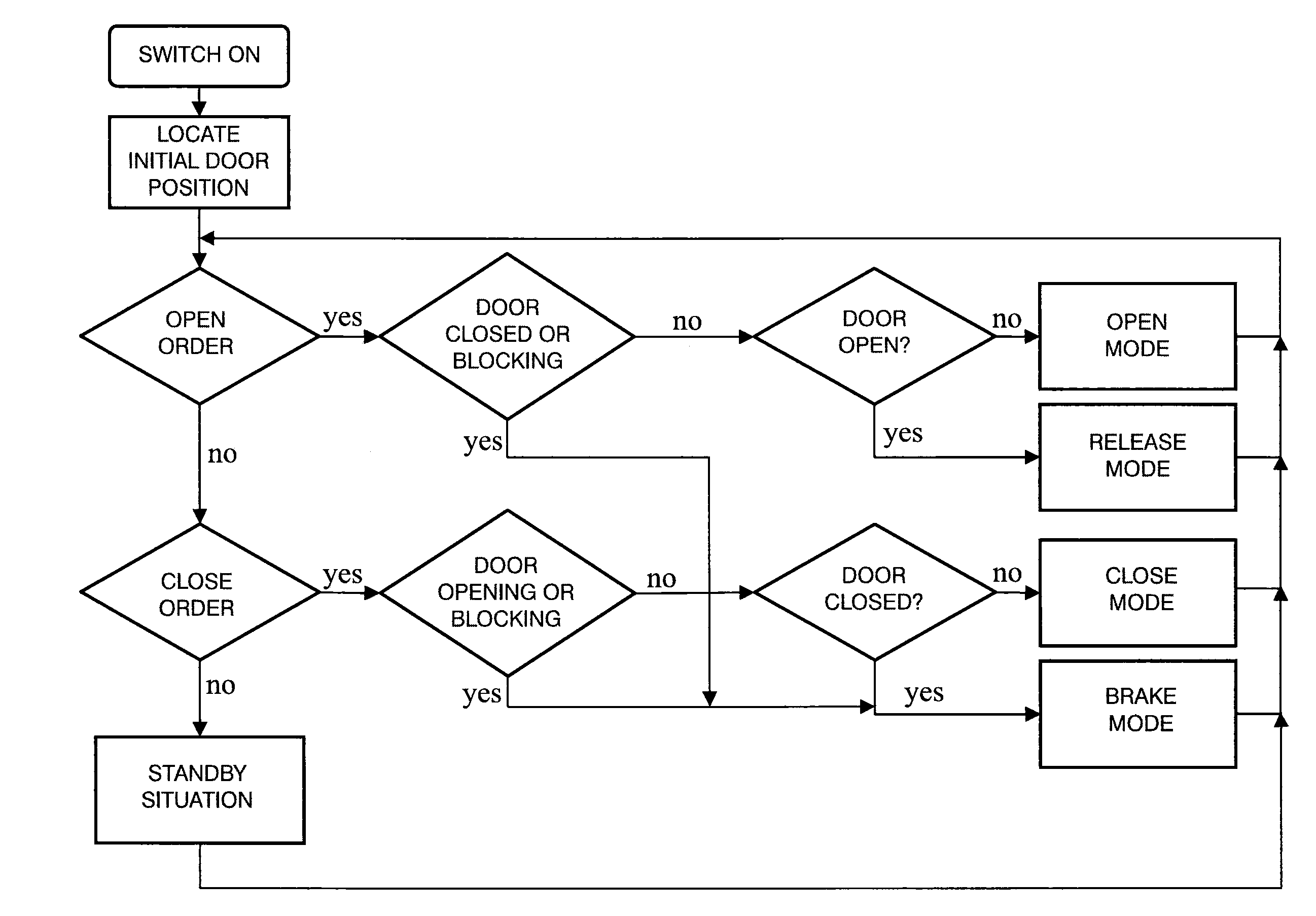
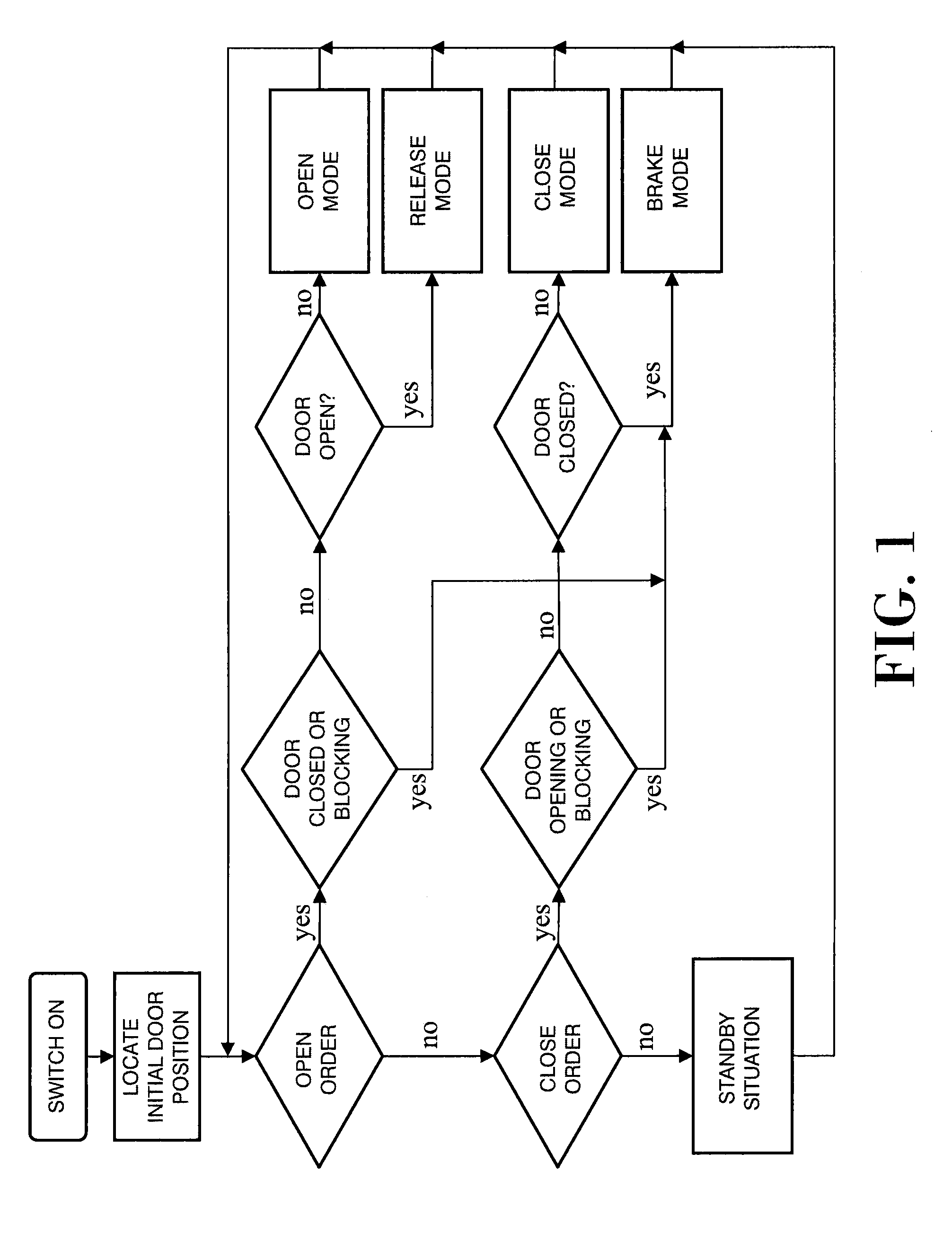
[0035]As can be seen in the drawings, particularly in FIG. 1, the operating method for operating doors of the invention goes through several working states or stages which determine the correct and safe working, covering all the possible situations and contingencies, all based, according to the preferred embodiment that is described below, on using the control system of the present invention, which comprises both power control means of the direct current motor (5) in charge of opening and closing said doors, as well as on the state and position control means thereof.

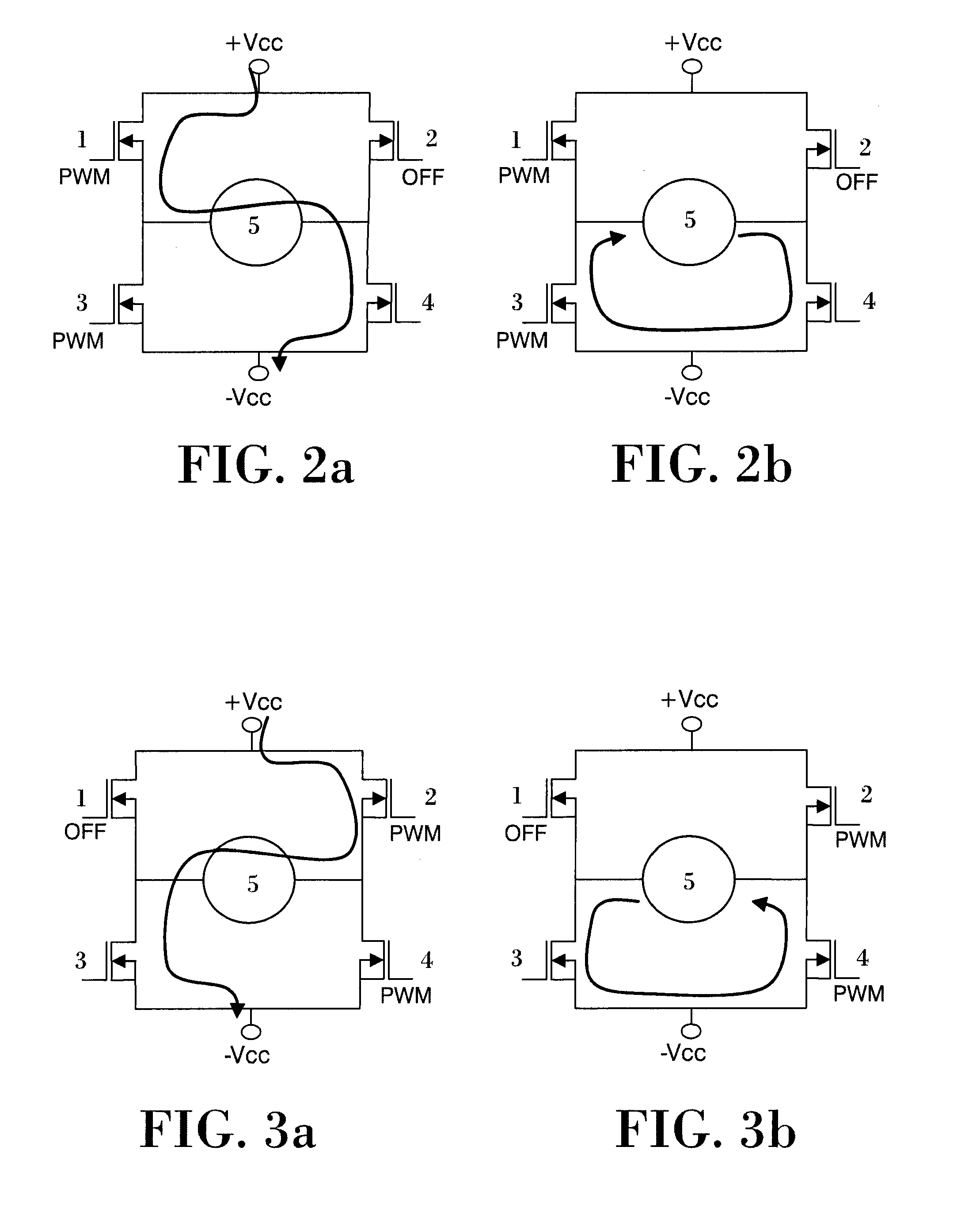
[0036]With respect to the power control means of the motor (1), and as can be seen in FIGS. 2 to 6, these means comprise a bridge of four transistors (1, 2, 3 and 4), specifically a bridge of the type referred to as a “full bridge” which, due to its operating mode, is capable of integrating the three stages of regulating the voltage of the motor (5), reversing the polarity or rotation and applying a brake in a single sta...


PUM


Abstract

The invention relates to a control system for controlling the movement of passenger access doors in railway vehicles and method for operating them based on said system, the object of which is to reduce the number of incidents occurring in said doors and it basically comprises power control means of the motor (5) operating the doors in charge of regulating the voltage, reversing the polarity or rotation of and applying a brake to said motor (5) and state and position control means of said doors which perform a triple-check of the state and position of said doors.

Description

TECHNICAL FIELD[0001]A control system for controlling the movement of passenger access doors in railway vehicles and a method for operating them based on said system.[0002]More specifically, the invention reduces the number of incidents occurring in said doors such that they reduce the disturbances caused in circulation for this reason, increasing reliability and reducing the corrective maintenance tasks.[0003]This reduction of the number of incidents is aimed, on one hand, at performing a specific operating method for operating the doors in each of their operational and non-operational phases, supported by a specific system for controlling the power of the motor and another one for controlling the state and position sensors of said doors.BACKGROUND[0004]The high number of doors that railway vehicles currently have and the high number of operations which said doors perform throughout the day is known.[0005]This high number of operations causes, on more occasions than desired, malfun...

Claims


Application Information

Patent Timeline
Patent Type & Authority Applications(United States)
IPC IPC(8): B61D19/02E05F15/00G05B19/042
CPCB61D19/026E05Y2400/31E05Y2400/354E05Y2900/51G05B19/0428G05B2219/2628E05F15/603H02P7/29E05Y2400/51E05Y2400/52E05Y2800/73E05F15/40H02P7/285G05B19/0426H02P7/04
Inventor GONZALEZ FERNANDEZ, JAVIERGARCIA SAN ANDRES, M. ANTONIASANCHO DE MINGO, CARLOSMUNOZ CONDES, PILARDE LA PENA LLERANDI, JAIMECEZON DOMINGUEZ, ANGEL R.RUIZ CANO, JOSE A.
Owner METRO DE MADRID
Why Eureka
Try Eureka