
Gutter cover apparatus

a technology of gutter cover and apparatus, which is applied in the direction of roof covering, roof covering, construction, etc., can solve the problems of clogging the drain holes or downspouts associated with the gutters, laborious removal of leaves or debris from the gutters, and high labor intensity, so as to achieve low manufacturing cost, easy installation, and low price

Inactive Publication Date: 2011-08-04
SNELL TODD
View PDF37 Cites 43 Cited by
  • Summary
  • Abstract
  • Description
  • Claims
  • Application Information

AI Technical Summary

Benefits of technology

[0017]It is another object of the present invention to provide a new and improved gutter cover apparatus which may be easily and efficiently manufactured and marketed.
[0024]Still a further object of the present invention is to provide a new and improved gutter cover apparatus that includes a drip edge so configured and constructed to help reduce staining of the gutter's front surface (i.e. eliminate “tiger striping”).

Problems solved by technology

At times, leaves and other debris can accumulate in the gutters and can clog the drain holes or downspouts associated with the gutters.
Removal of such leaves or debris from a roof gutter is laborious, time consuming and possibly hazardous.
The drainage perforations in the sheet metal protector are relatively large requiring frequent removal and cleaning of the gutter.
Because of its concave shape, and the upward cant of the swedges defining the openings in this form of cover, the cover tends to become more easily clogged by clinging wet leaves than is otherwise desired reducing its effectiveness.
No means are provided in this arrangement for preventing leaves or other debris from being plastered against the slit openings, sticking in place, and reducing drainage effectiveness.
Such plastic gutter protectors are relatively expensive to fabricate and are susceptible to discoloration and / or cracking over time from exposure to sunlight.
Thus, while the foregoing body of prior art indicates it to be well known to use different types of gutter covers, the prior art described above does not teach or suggest a gutter cover apparatus which has the following combination of desirable features: (1) provides a cover for gutter that is easy to install, relatively inexpensive to fabricate, and is durable over time; (2) provides a gutter cover that includes an enhanced number of drainage openings per unit / area thereby efficiently draining rainwater runoff into a roof gutter all of the while protecting the gutter from filling with leaves or other debris; (3) provides a gutter cover that includes means for preventing wet leaves or other debris from sticking in place over the openings in the gutter cover and thereby reducing its effectiveness; (4) provides means for retarding the flow of water runoff across the surface of the cover to help reduce the velocity of the flowing water and help lift debris away from the surface of the cover; (5) provides a gutter cover that includes means for reducing the amount of debris lodging behind the gutter structure; and (6) provides a gutter cover that includes a front drip edge so configured and constructed to reduce staining of the gutter's front surface (i.e. eliminate “tiger striping”).

Method used


Image

  • Gutter cover apparatus
  • Gutter cover apparatus
  • Gutter cover apparatus

Examples


Embodiment Construction

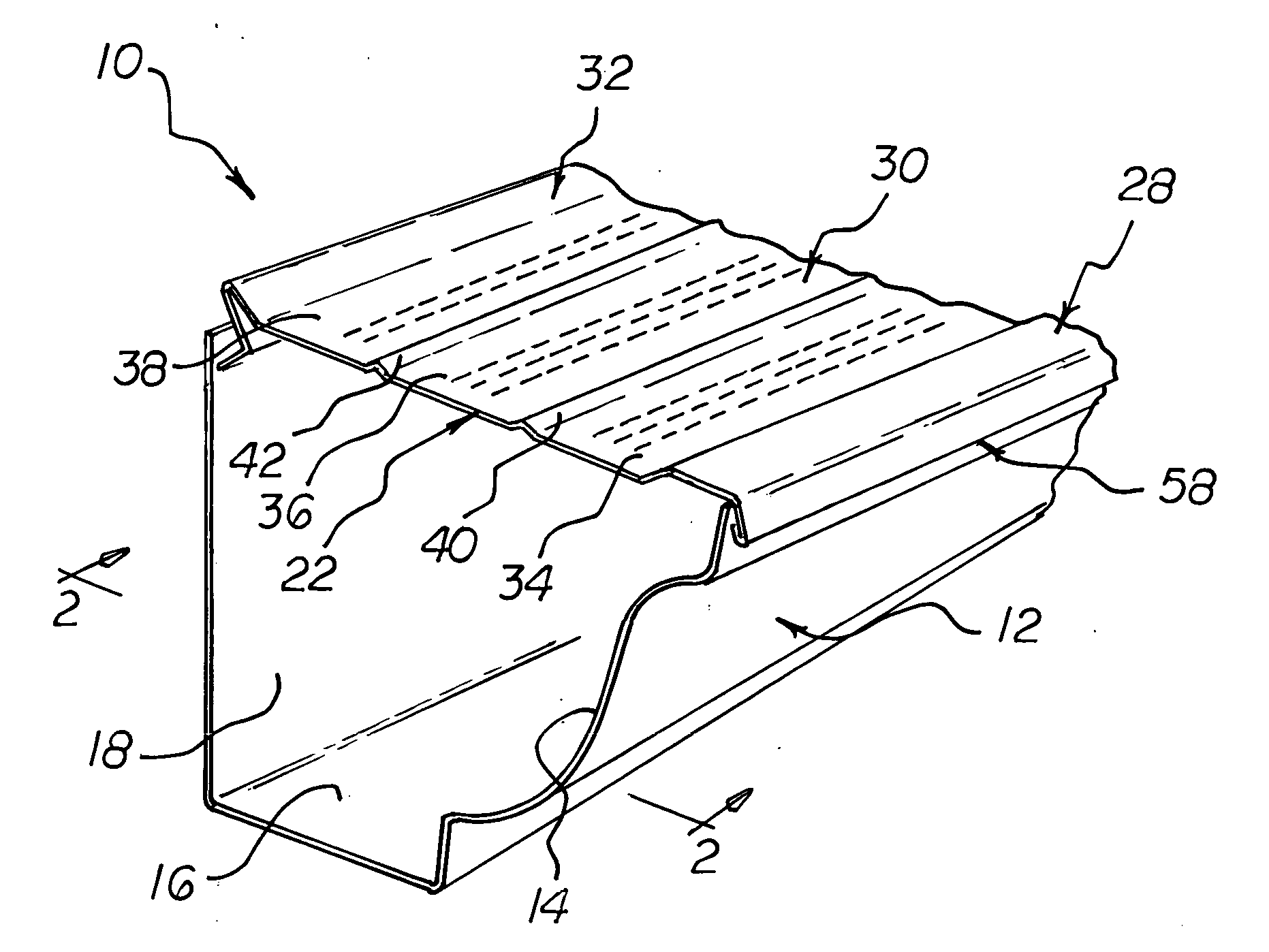
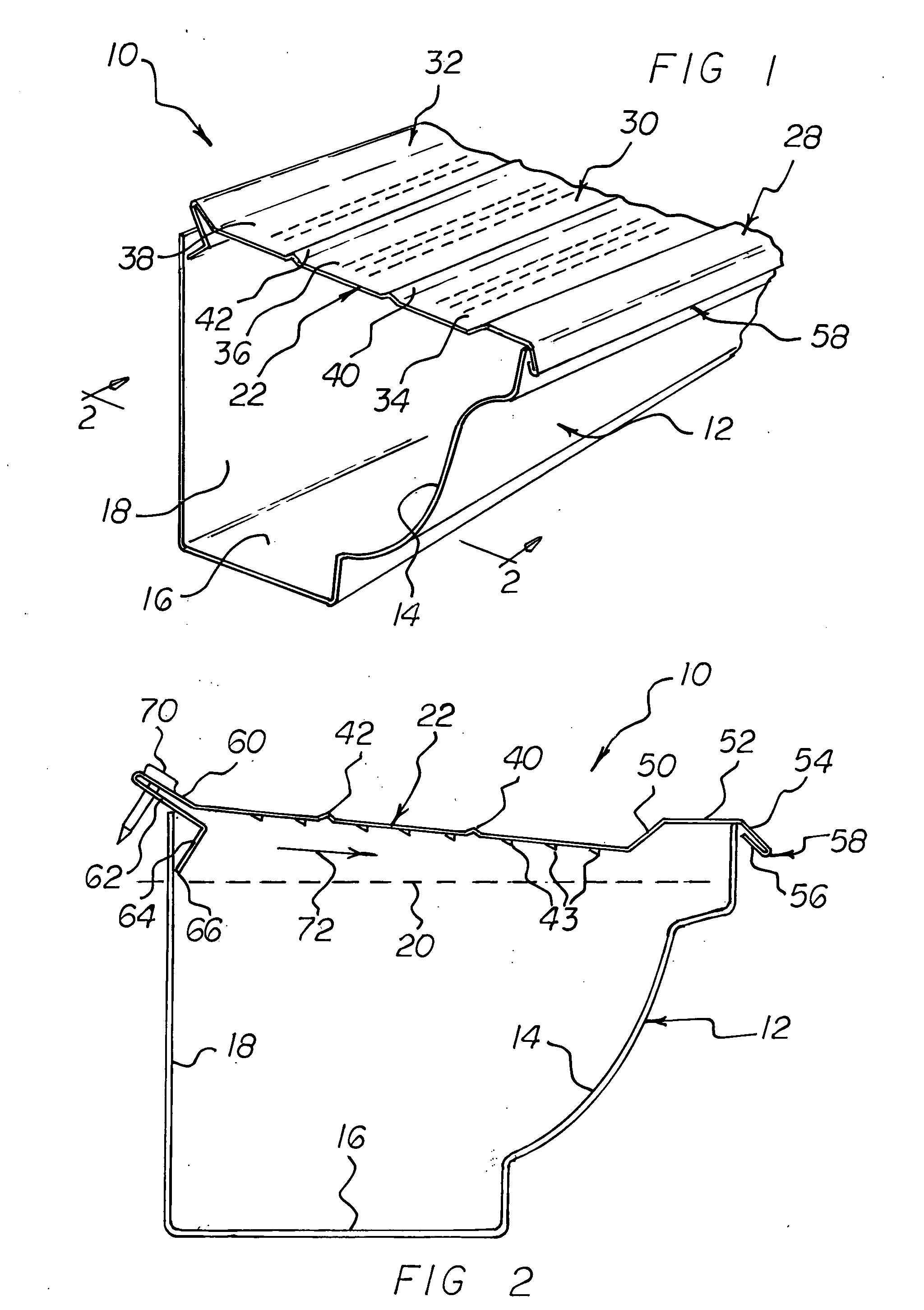
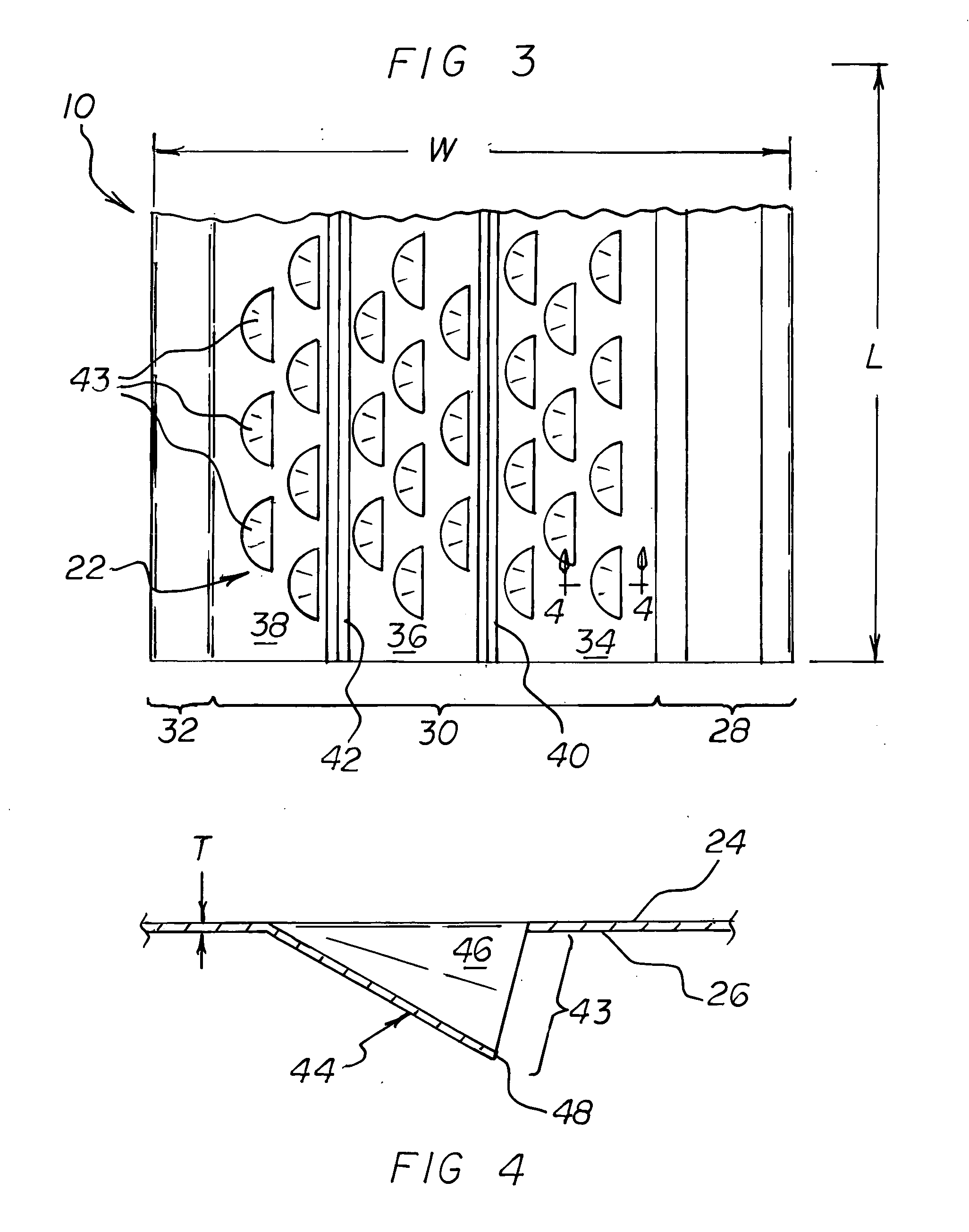
[0037]With reference to the drawings, a new and improved gutter cover apparatus embodying the principles and concepts of the present invention will be described.

[0038]Turning initially to FIGS. 1-4, there is shown a preferred embodiment of the gutter cover apparatus of the invention generally designated by reference numeral 10. As shown in FIGS. 1 and 2, gutter cover apparatus 10 is adapted to be installed on top of a section of conventional gutter construction wherein the gutter 12 includes a front wall 14, a bottom wall 16, and a rear wall 18. It will be appreciated that gutter 12 may be suitably attached to a building structure (not shown) adjacent the roof eave of a building structure in order to collect runoff rainwater from the roof. One typical way of suitably attaching the gutter to the fascia board adjacent the roof eave is to use a conventional gutter hanger spike (not shown) suitably driven through the gutter and into the fascia board along an imaginary axis indicated by ...


PUM

PropertyMeasurementUnit
widthaaaaaaaaaa
widthaaaaaaaaaa
widthaaaaaaaaaa

Abstract

A gutter cover apparatus a comprising a relatively thin, elongated generally planar sheet member, preferably of metallic material, suitably sized and configured to fit over and cover the top of a conventional roof gutter. The elongated sheet member has a longitudinal front edge portion, a longitudinal rear edge portion, and a generally planar intermediate portion therebetween. The intermediate portion, in turn, is characterized by first and second upstanding longitudinal spaced ridges or protuberances, spaced from each other and extending generally parallel to each other and to the front edge portion and the rear edge portion of the sheet member, substantially the full length thereof. The first and second upstanding spaced ridges define first, second and third drainage zones each containing a pattern of staggered rows of openings, each one of which opening is in the form of downwardly depending semi-cylindrical or other arcuate-shaped spout opening below the bottom surface of the sheet member and facing forwardly thereof. The rear longitudinal edge portion of the sheet member is bent suitably to form an upstanding “spoiler” or debris blocking section downwardly terminating in a longitudinally extending distal edge defining a bearing surface for the rear portion of the sheet member. The forward longitudinal edge portion of the sheet member is raised upwardly with respect to the drainage zones on the intermediate portion of the sheet member to define a downwardly directed “drip lip” and a bearing surface for the front of the sheet member with respect to the front edge of the gutter to which operatively it may be attached.

Description

BACKGROUND OF THE INVENTION[0001]1. Field of the Invention[0002]The present invention relates generally to gutter covers, and, more particularly, to a unique gutter cover apparatus for permitting rainwater to enter a roof gutter without permitting leaves or other debris from entering the gutter and causing clogging.[0003]2. Description of the Prior Art[0004]Gutters are placed next to the edge of a roof to collect water runoff and to direct the runoff away from a building structure. At times, leaves and other debris can accumulate in the gutters and can clog the drain holes or downspouts associated with the gutters. Removal of such leaves or debris from a roof gutter is laborious, time consuming and possibly hazardous. To overcome these challenges, gutter covers, shields or protectors can be installed over the gutters to prevent debris from accumulating in the gutters without impeding the flow of rainwater into the gutter trough. Throughout the years, a number of innovations have bee...

Claims


Application Information

Patent Timeline
Patent Type & Authority Applications(United States)
IPC IPC(8): E04D13/076
CPCE04D13/076
Inventor SNELL, TODD
Owner SNELL TODD
Learn More