
Hinge and door unit

a technology of hinges and units, applied in the field of hinges, can solve the problems of reducing working efficiency, unable to apply the structure to the side door without modification, etc., and achieve the effects of convenient engagement and disengagement, improved durability of the hold-stay members, and convenient fastening

Inactive Publication Date: 2011-08-04
CATEPILLAR SARL
View PDF19 Cites 11 Cited by
  • Summary
  • Abstract
  • Description
  • Claims
  • Application Information

AI Technical Summary

Benefits of technology

The present invention relates to a hinge that includes a plurality of one-side hinge plate portions and a plurality of mounting plate portions that are integrally body with the one-side hinge plate portions. The hinge also includes an open-angle limiting mechanism that stops, at a specific angle, opening movement of the opposing-side hinge plate portions with respect to the one-side hinge plate portions. The open-angle limiting mechanism includes a plurality of hold-stay members that have fitting portions and catching portions that engage with or disengage from lock members. The hinge also includes a bracket that holds the one-side hinge plate portions and the mounting plate portions in place. The hinge is durable and easy to use, and the open-angle limiting mechanism ensures that the hinge stays in the desired position.

Problems solved by technology

However, such a structure cannot be applied to a side door without modification.
However, as the vertical dimension of a work machine is large, it often happens that an operator cannot reach the hold-stay or rod of the upper hinge and has to prepare a ladder or the like, resulting in reduced working efficiency.

Method used


Image

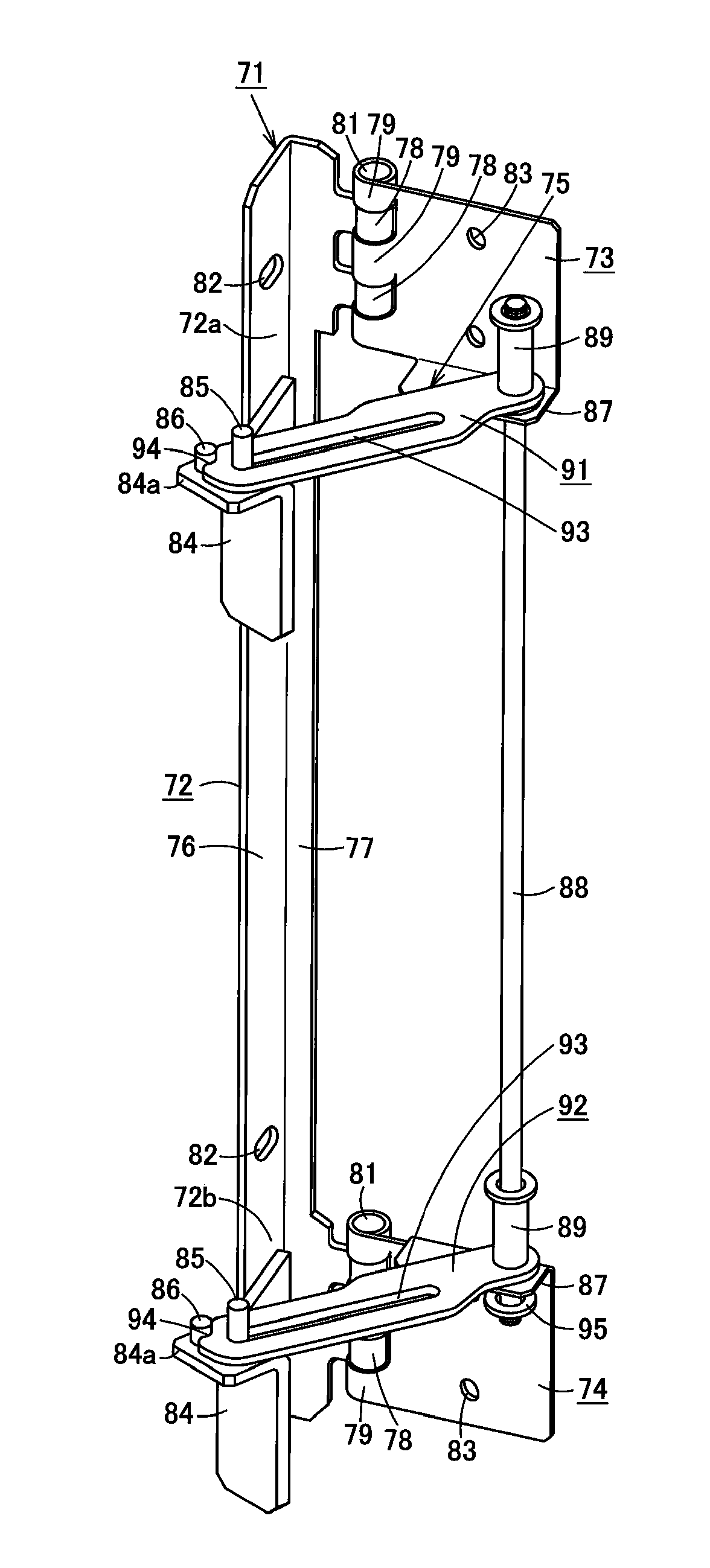
  • Hinge and door unit
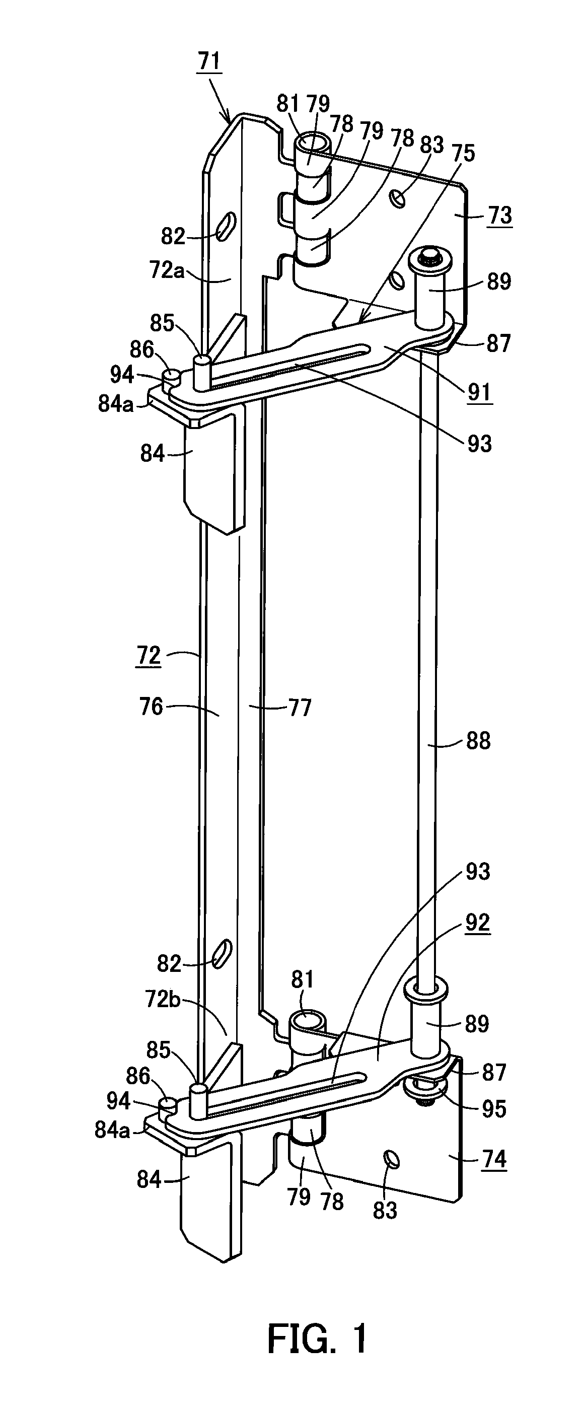
  • Hinge and door unit
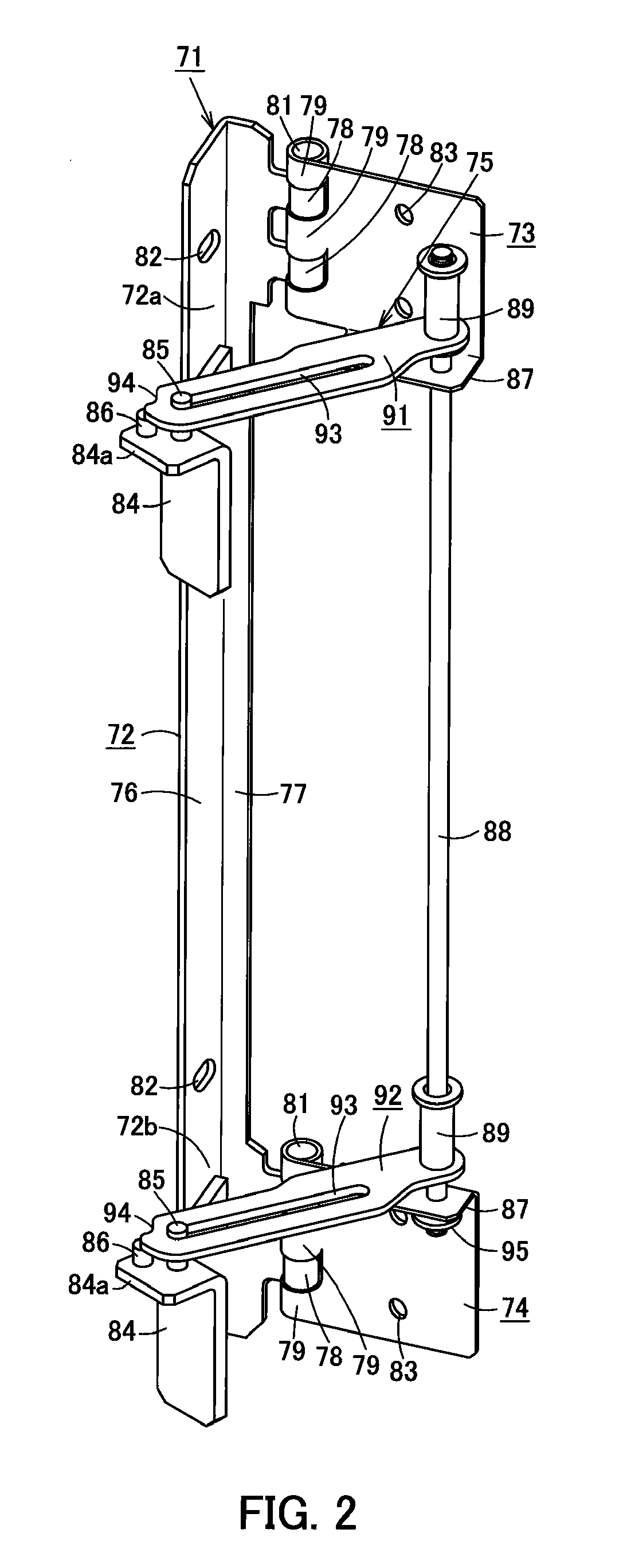
  • Hinge and door unit

Examples


Embodiment Construction

[0032]Next, the present invention is explained in detail hereunder, referring to an example thereof shown in FIGS. 1 to 9.

[0033]FIG. 9 illustrates a hydraulic excavator 10, which is a work machine. The hydraulic excavator 10 includes a lower structure 11, an upper structure 12, a cab 13, a work equipment 14, and a power system 15 that includes an engine. The cab 13, the work, equipment 14, and the power system 15 are mounted on the upper structure 12, which is rotatably mounted on the lower structure 11. The power system 15 is covered, by a top cover 16, side doors 17, and other such components.

[0034]FIGS. 3 to 6 illustrate a door panel 20 of a side door 17. The door panel 20 includes an outer panel 21, an inner panel 23, and a foamed material 24. The inner panel 23 is formed by means of press molding so as to have an uneven surface with recessed portions and raised portions. The recessed portions are fixed to the inner surface of the outer panel 21, and a space 22 is formed between...


PUM


Abstract

A hinge enabling a plurality of hold-stay members to automatically lock when the door is fully open, increasing the durability of the hinge, and enabling easy release of the hold-stay members. A hinge includes a one-side hinge plate, a plurality of opposing-side hinge plate portions provided along the lengthwise direction of the hinge plate and supported by it, and an open-angle limiting mechanism for stopping, at a specific angle, opening movement of the opposing-side hinge plate portions.

Description

CROSS REFERENCE TO PRIOR APPLICATIONS[0001]This application is a U.S. National Phase application under 35 U.S.C. § 371 of International Application No. PCT / JP2010 / 063377, filed on Aug. 6, 2010 and claims benefit of priority to Japanese Patent Application No, 2009-196811, filed on Aug. 27, 2009. The International Application was published in Japanese on Mar. 3, 2011 as WO 2011 / 024628 A1 under PCT Article 21(2. All of these applications are herein incorporated by reference.TECHNICAL FIELD[0002]The present invention relates to a hinge for attaching a door panel to a frame. The invention also relates to a door unit that can be opened and closed freely by means of the hinge.BACKGROUND OF THE INVENTION[0003]FIG. 11 illustrates a hydraulic excavator 10, which is a work machine. The hydraulic excavator 10 includes a lower structure 11, an upper structure 12, a cab 13, a work equipment 14, and a power system 15 that includes an engine. The cab 13, the work equipment 14, and the power system...

Claims


Application Information

Patent Timeline
Patent Type & Authority Applications(United States)
IPC IPC(8): E05D11/06E06B3/36E05C17/22
CPCE02F9/00E02F9/0891Y10T16/551E05C17/14E05C17/025
Inventor UTO, RYOJIGOTO, TAKAHIRO
Owner CATEPILLAR SARL
Learn More